INSTALLING YOUR NEW RECORDER | EN 9 |
Basic Connections
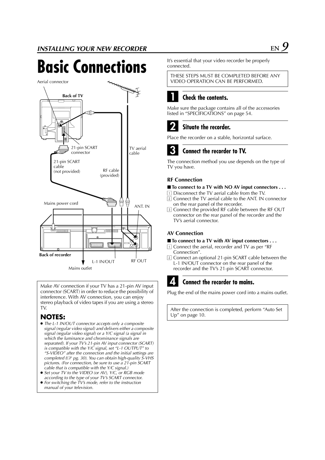
Aerial connector
Back of TV
TV aerial | |
connector | cable |
| |
cable | RF cable |
(not provided) | |
| (provided) |
It’s essential that your video recorder be properly connected.
THESE STEPS MUST BE COMPLETED BEFORE ANY VIDEO OPERATION CAN BE PERFORMED.
A Check the contents.
Make sure the package contains all of the accessories listed in “SPECIFICATIONS” on page 54.
B Situate the recorder.
Place the recorder on a stable, horizontal surface.
C Connect the recorder to TV.
The connection method you use depends on the type of TV you have.
RF Connection
8To connect to a TV with NO AV input connectors . . .
Mains power cord
Back of recorder
ANT. IN
ADisconnect the TV aerial cable from the TV.
BConnect the TV aerial cable to the ANT. IN connector on the rear panel of the recorder.
CConnect the provided RF cable between the RF OUT connector on the rear panel of the recorder and the TV’s aerial connector.
AV Connection
8To connect to a TV with AV input connectors . . .
A Connect the aerial, recorder and TV as per “RF |
Connection”. |
B Connect an optional |
RF OUT |
Mains outlet
Make AV connection if your TV has a
NOTES:
●The
●Set your TV to the VIDEO (or AV), Y/C, or RGB mode according to the type of your TV’s SCART connector.
●For switching the TV’s mode, refer to the instruction manual of your television.
recorder and the TV’s |
D Connect the recorder to mains.
Plug the end of the mains power cord into a mains outlet.
After the connection is completed, perform “Auto Set Up” on page 10.