RX-8040B
For the remote control / Pour la télécommande
Mises en garde, précautions et indications diverses
Introduction
Features
Precautions
Table of Contents
Remote Control
Parts Identification
Display
How to open the front door
Front Panel
Press down on PUSH-OPEN
DVD MULTI, DVD, VCR 1, VCR 2, Video
Monitor OUT
Rear Panel
Phono
Getting Started
Checking the Supplied Accessories
Connecting the FM and AM Antennas
AM antenna connections
Speaker connections
Connecting the Speakers and Subwoofer
Connecting the subwoofer
Center speaker
Enhance your audio system
Power amplifier Surround back speaker
Placing speakers
CD player
Connecting Audio/Video Components
Analog connections
CD recorder
Video component connections
Cassette deck
MD recorder
If your video components have an AV Compulink jack
DBS tuner
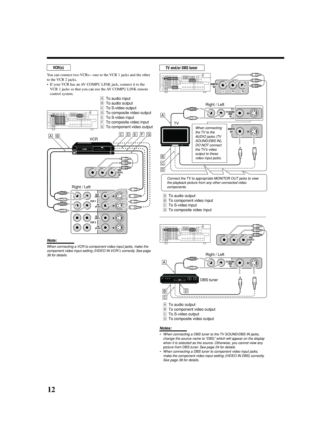
VCRs
TV and/or DBS tuner
DVD player
When you connect a DVD player with stereo output jacks
DVD player
Digital connections
Connecting the RF Rod Antenna IR Signal Transmitter
Setting up the RF rod antenna
Digital output terminal
Putting Batteries in the Remote Control
Connecting the Power Cord
Find a place where you can attach the IR signal transmitter
Setting up the IR signal transmitter
Connection Å
Multi-room Operations
Required Connections for Zone
Connection ı
Press STANDBY/ON
Basic Operating Procedure for Zone
Press Audio Power on
Set Zone 1/ZONE 2 selector to Zone
ZONE2 appears
Press Zone 2 ON/OFF to activate Zone
Playback
Last Zone 2 source appears
Zone 1 Main Room Operations
Turning the Power On and Off Standby
Canceling the Zone 1 Operations
For Zone 1 operations
Selecting the Zone 1 Source to Play
Speaker and signal indicators on the display
When analog input is selected Always lights up
Press one of the source selection buttons
Selecting different sources for picture and sound
Adjusting the Zone 1 Volume
Listening with headphones only
To use the speakers connected to the FRONT1 Speakers
Press Input Digital to select Dgtl Auto
Selecting the Analog or Digital Input Mode
To select the analog input mode again
Making Sounds Natural
Setting the Dynamic Range
Turning Analog Direct On and Off
Press Analog Direct so that a Direct appears on the display
Changing the Display Brightness
Reinforcing the Bass
Muting the Zone 1 Sound
Recording a source
Using the Sleep Timer
Basic adjustment auto memory
For Zone 2 operations
Zone 2 indicator lights up
Zone 2 Sub-room Operations
Last Zone
Press STANDBY/ON again
Canceling the Zone 2 Operations
Zone 2 ON/OFF again the Zone 2 indicator lights up
Standby lamp lights up
Ex. When DVD is selected as the source
Selected source name Zone 2 volume Level appears
Muting the Zone 2 Sound
Speakers Zone 2 indicator lights up on the display
Speakers Zone 2 indicator lights up
Set Zone 1/ZONE 2 selector to Zone
When operating for Zone
Tuning in to Stations Manually
Tuning in to the frequency
Receiving Radio Broadcasts
Selecting the FM Reception Mode
Using Preset Tuning
Press the 10 keys to select a preset channel number
While listening to an FM station, press FM Mode
Channel number
Basic Settings
Press Quick Speaker Setup
Press in Multi JOG Push SET
Size Speaker Distance
Speakers channels number and the size
Room size and the speaker distance
Items To do See
Push in Multi JOG Push SET
Press Setting
Setting the speakers
Press Exit
Select which measuring unit you use
Setting the speaker distance
Setting the bass sounds
Select one of the following
Dual Mono SUB
Selecting the main or sub-channel
Dual Mono Main
Dual Mono ALL
Digital optical terminals-DGTL in Optical
Setting the digital input terminals
Digital coaxial terminal-DGTL in Coax
Memorizing the volume level for each source
Setting the component video input
Setting the Zone 2/Speakers
Video VCR1 S/C
Adjusting Sound
Basic Adjustment Items
Adjusting the equalization patterns
Basic Procedure
Press Adjust
Adjusting the speaker output levels
Liveness
Effect
Roomsize
Dolby Digital*1 and Dolby Surround
Using the Surround Modes
Reproducing Theater Ambience Introducing the Surround Modes
Dolby Pro Logic
DTS Extended Surround DTS-ES
Dolby Digital EX
Dolby Digital 5.1CH
DTS 96/24
Activating the Surround Modes
Press Surround to activate the Surround mode
To cancel the Surround modes
Select and play any source excluding
EX/ESON
Activating the EX/ES/PLIIx setting
EX/ESAUTO
PLIIx Music
Surround Modes Applicable to the Various Software
Incoming Signal Type
EX/ES/PLIIx Available Surround Mode
Deactivated
PLIIx Music
Virtual 6.1-channel surround
3D Headphone mode-3D H Phone
Introducing the DSP Modes
Using the DSP Modes
Reproducing the Sound Field
Activating the DSP Modes
To cancel the DSP modes
To adjust the effect level except All Channel Stereo, see
Select and play any source excluding DVD Multi
Multi indicator also lights up
Using the DVD Multi Playback Mode
Activating the DVD Multi Playback Mode
Press DVD Multi so that DVD appears on the display
Automatic Source Selection
Compu Link Remote Control System
Remote Control through the Remote Sensor on the Receiver
Press the play 3 button on the CD player
Automatic Power Off Standby
Recorder at the same time
Synchronized Recording Only for Zone 1 Operations
Connections 2 AV Compu Link Connection
AV Compu Link Remote Control System
Connections 1 IR Signal Transmitter Connection
On the rear panel
This receiver Equipment Component
Connections 3 Video Cable Connection
This receiver Equipment
Video cable To Video Input
Automatic Power On/Off Standby
One-Touch DVD Play
Sound control section Amplifier
Operating JVC’s Audio/Video Components
Operating Audio Components
Tuner
Turntable
CD player
CD changer
CD recorder
DVD player
Operating Video Components
VCR connected to the VCR 1 jacks
Operating Other Manufacturers’ Equipment
Try to operate your Catv converter or DBS tuner by pressing
Press and hold DVD Power Press VCR
Release DVD Power Using buttons 1-9,
If more than one code is listed for your
Press and hold DVD Power Press DVD
Press CD
For Catv converter
For TV
Manufacturer Codes
For DBS tuner
Multi-room operations Zone 1/Zone
Troubleshooting
FM/AM Problem Possible Cause Solution
General
Problem Possible Cause Solution
Surround and DSP modes
FM tuner IHF
Audio
Video
AM tuner
Limited WARRANTYAUDIO-2
Authorized Service Centers
RX-8040B AUDIO/VIDEO Control Receiver
Recepteur DE Commande AUDIO/VIDEO
Mises en garde, précautions et indications diverses
English
Tuning in to Stations Manually
Zone
Headphone Speakers 1 2 Zone
DVD MULTI, DVD, VCR 1, VCR 2, Video
Right Left
Connect the supplied FM antenna as temporary measure to
FRONT1 and FRONT2
Placing speakers
Connecting Audio/Video Components
Cassette deck
DBS
DVD player
Connecting the RF Rod Antenna and IR Signal Transmitter
Connecting the Power Cord
Multi-room Operations
Basic Operating Procedure for Zone
Press Zone 2 ON/OFF to activate Zone
Zone 1 Main Room Operations
DVD Multi VCR Video TV Sound Phono CDR TAPE/MD DBS
DVD Multi
Digital Speakers
Attenuating the Input Signal
Changing the Source Name
Using the Sleep Timer
Zone 2 Sub-room Operations
Canceling the Zone 2 Operations
Phono CDR TAPE/MD DBS
Activating the Zone 2 Front
Receiving Radio Broadcasts
Using Preset Tuning
Basic Settings
LS/RS Subwfr
Basic Procedure
11 ft
With Surround Activated
Setting the digital input terminals
Setting the component video input
Items To do
Basic Procedure
Effect
Using the Surround Modes
DTS*2
Control
Activating the EX/ES/PLIIx setting
Linear PCM
DTS Dual Mono
Using the DSP Modes
Zone Standby TV/CATV/DBS
Zone
Compu Link Remote Control System
Recorder at the same time
AV Compu Link Remote Control System
Connections 3 Video Cable Connection
Automatic Power Off Standby
Operating JVC’s Audio/Video Components
Stop operations
Fast-wind the tape from right to left
DVD Zone
Operating Other Manufacturers’ Equipment
Press and hold DVD Power
REW Play
Initial setting
Zone
Surround and DSP modes
70 dB/78 dB at OUT REC
EN, FR Victor Company of JAPAN, Limited 0504MWMMDWJEIN