2 CONTROLS AND CONNECTORS
2-3 Rear Panel
1
CAM SW | ALARM |
|
| ALARM | COM |
|
|
|
| SERIES/CLOCK | ||||||||||||||||||||||||||||||||||||||||
| OUT |
| IN |
|
| REC | OUT |
|
|
| WARNING |
|
|
|
|
|
| |||||||||||||||||||||||||||||||||
|
|
|
|
|
|
|
|
| ||||||||||||||||||||||||||||||||||||||||||
|
|
|
|
|
|
| COM |
|
|
|
|
| ALARM |
|
|
|
| TAPE |
|
|
|
|
| /REC |
|
|
|
|
|
|
|
|
|
| ||||||||||||||||
|
|
|
|
|
|
|
|
|
|
|
|
|
|
|
|
|
|
|
|
|
| |||||||||||||||||||||||||||||
|
|
|
|
|
|
|
|
|
|
|
|
|
|
|
|
| RESET |
|
| END OUT |
|
|
| OUT |
| IN | OUT | |||||||||||||||||||||||
|
|
|
|
|
|
|
|
|
|
|
|
|
|
|
|
|
|
|
|
|
|
|
|
|
|
|
|
|
|
|
|
|
|
|
|
|
|
|
|
|
|
|
|
|
|
|
|
|
|
|
|
|
|
|
|
|
|
|
|
|
|
|
|
|
|
|
|
|
|
|
|
|
|
|
|
|
|
|
|
|
|
|
|
|
|
|
|
|
|
|
|
|
|
|
|
|
|
|
|
|
|
|
|
|
|
|
|
|
|
|
|
|
|
|
|
|
|
|
|
|
|
|
|
|
|
|
|
|
|
|
|
|
|
|
|
|
|
|
|
|
|
|
|
|
|
|
|
|
|
|
|
|
|
|
|
|
|
|
|
|
|
|
|
|
|
|
|
|
|
|
|
|
|
|
|
|
|
|
|
|
|
|
|
|
|
|
|
|
|
|
|
|
|
|
|
|
|
|
|
|
|
|
|
|
|
|
|
|
|
|
|
|
|
|
|
|
|
|
|
|
|
|
|
|
|
|
|
|
|
|
|
|
|
|
|
|
|
|
|
|
|
|
|
|
|
|
|
|
|
|
|
|
|
|
|
|
|
|
|
|
|
|
|
|
|
|
|
|
|
|
|
|
|
|
|
|
|
|
|
|
|
|
|
|
|
|
|
|
|
|
|
|
|
|
|
|
|
|
|
|
|
|
|
|
|
2 3 4
|
|
|
|
|
| MIC | VIDEO | AUDIO |
|
|
|
|
|
| IN |
| |
|
|
|
|
|
|
|
| |
|
|
|
|
|
|
| IN | IN |
CAM SW | ALARM | ALARM | COM | SERIES/CLOCK | REMOTE |
|
| |
OUT | IN | REC OUT | WARNING |
|
| |||
COM | ALARM | TAPE | /REC | IN OUT |
|
| ||
| RESET | END OUT OUT |
|
|
| |||
OUT
OUT
7 6 5
Connecting the wires to the terminals 8
1. Hold the button down and insert the wire over the top of the
terminal.
button 2. Release the button to lock the wire in the
terminal.
8
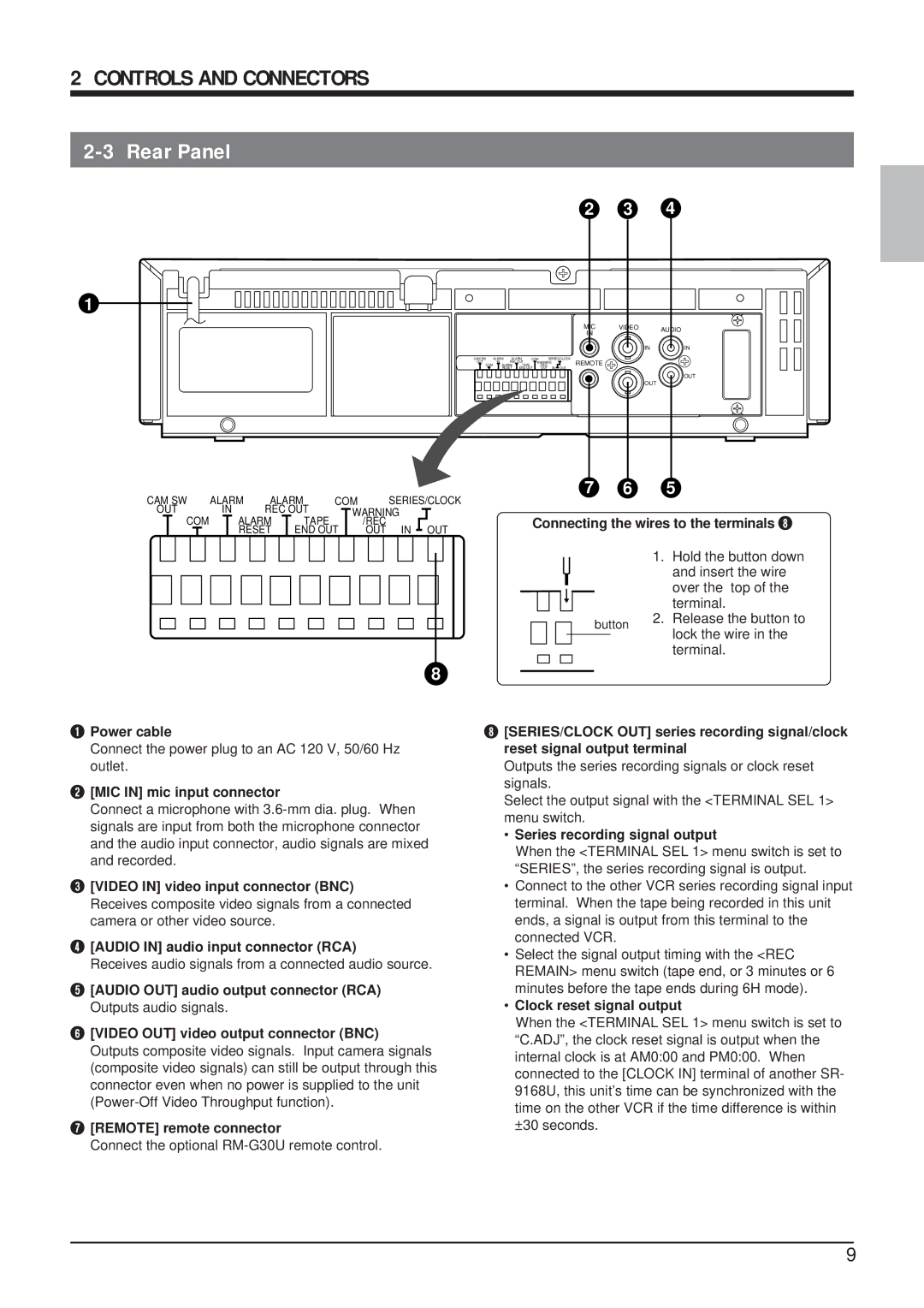
1Power cable
Connect the power plug to an AC 120 V, 50/60 Hz outlet.
2[MIC IN] mic input connector
Connect a microphone with
3[VIDEO IN] video input connector (BNC) Receives composite video signals from a connected camera or other video source.
4[AUDIO IN] audio input connector (RCA)
Receives audio signals from a connected audio source.
5[AUDIO OUT] audio output connector (RCA) Outputs audio signals.
6[VIDEO OUT] video output connector (BNC) Outputs composite video signals. Input camera signals (composite video signals) can still be output through this connector even when no power is supplied to the unit
7[REMOTE] remote connector
Connect the optional
8[SERIES/CLOCK OUT] series recording signal/clock reset signal output terminal
Outputs the series recording signals or clock reset signals.
Select the output signal with the <TERMINAL SEL 1> menu switch.
•Series recording signal output
When the <TERMINAL SEL 1> menu switch is set to “SERIES”, the series recording signal is output.
•Connect to the other VCR series recording signal input terminal. When the tape being recorded in this unit ends, a signal is output from this terminal to the connected VCR.
•Select the signal output timing with the <REC REMAIN> menu switch (tape end, or 3 minutes or 6 minutes before the tape ends during 6H mode).
•Clock reset signal output
When the <TERMINAL SEL 1> menu switch is set to “C.ADJ”, the clock reset signal is output when the internal clock is at AM0:00 and PM0:00. When connected to the [CLOCK IN] terminal of another SR- 9168U, this unit’s time can be synchronized with the time on the other VCR if the time difference is within ±30 seconds.
9