10. OPTIONAL SA-K97U RS-232C INTERFACE BOARD
2-3 Commands for VCR status verification
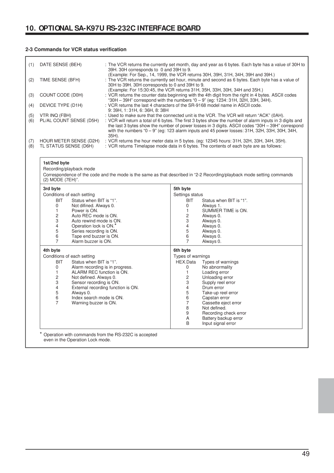
(1) | DATE SENSE (BEH) | : The VCR returns the currently set month, day and year as 6 bytes. Each byte has a value of 30H to |
|
| 39H. 30H corresponds to 0 and 39H to 9. |
|
| (Example: For Sep., 14, 1999, the VCR returns 30H, 39H, 31H, 34H, 39H and 39H.) |
(2) | TIME SENSE (BFH) | : The VCR returns the currently set hour, minute and second as 6 bytes. Each byte has a value of |
|
| 30H to 39H. 30H corresponds to 0 and 39H to 9. |
|
| (Example: For 15:30:45, the VCR returns 31H, 35H, 33H, 30H, 34H and 35H.) |
(3) | COUNT CODE (D0H) | : VCR returns the counter data beginning with the 4th digit from the right in 4 bytes. ASCII codes |
|
| “30H – 39H” correspond with the numbers “0 – 9” (eg: 1234: 31H, 32H, 33H, 34H). |
(4) | DEVICE TYPE (D1H) | : VCR returns the last 4 characters of the |
|
| 9: 39H, 1: 31H, 6: 36H, 8: 38H |
(5) | VTR INQ (FBH) | : Used to make sure that the connected unit is the VCR. The VCR will return “ACK” (0AH). |
(6) | PL/AL COUNT SENSE (D5H) | : VCR will return a total of 6 bytes. The first 3 bytes show the number of alarm inputs in 3 digits and |
|
| the last 3 bytes show the number of power losses in 3 digits. ASCII codes “30H – 39H” correspond |
|
| with the numbers “0 – 9” (eg: 123 alarm inputs and 45 power losses: 31H, 32H, 33H, 30H, 34H, |
|
| 35H). |
(7) | HOUR METER SENSE (D2H) | : VCR returns the hour meter data in 5 bytes. (eg: 12345 hours: 31H, 32H, 33H, 34H, 35H). |
(8) | TL STATUS SENSE (D6H) | : VCR returns Timelapse mode data in 6 bytes. The contents of each byte are as follows: |
1st/2nd byte
Recording/playback mode
Correspondence of the code and the mode is the same as that described in
(2) MODE (7EH)”.
3rd byte |
| 5th byte |
|
Conditions of each setting | Settings status | ||
BIT | Status when BIT is “1”. | BIT | Status when BIT is “1”. |
0 | Not difined. Always 0. | 0 | Always 1. |
1 | Power is ON. | 1 | SUMMER TIME is ON. |
2 | Auto REC mode is ON. | 2 | Always 0. |
3 | Auto rewind mode is ON. | 3 | Always 0. |
4 | Operation lock is ON.* | 4 | Always 0. |
5 | Series recording is ON. | 5 | Always 0. |
6 | Tape end buzzer is ON. | 6 | Always 0. |
7 | Alarm buzzer is ON. | 7 | Always 0. |
|
|
|
|
4th byte |
| 6th byte |
|
Conditions of each setting | Types of warnings | ||
BIT | Status when BIT is “1”. | HEX.Data | Types of warnings |
0 | Alarm recording is in progress. | 0 | No abnormality |
1 | ALARM REC function is ON. | 1 | Loading error |
2 | Not defined. Always 0. | 2 | Unloading error |
3 | Sensor recording is ON. | 3 | Supply reel error |
4 | External recording function is ON. | 4 | Drum error |
5 | Always 0. | 5 | |
6 | Index search mode is ON. | 6 | Capstan error |
7 | Warning buzzer is ON. | 7 | Cassette eject error |
|
| 8 | Not defined. |
|
| 9 | Recording check error |
|
| A | Battery backup error |
|
| B | Input signal error |
|
|
|
|
*Operation with commands from the
49