RX+ A
RX– B
TX+ C
TX– D
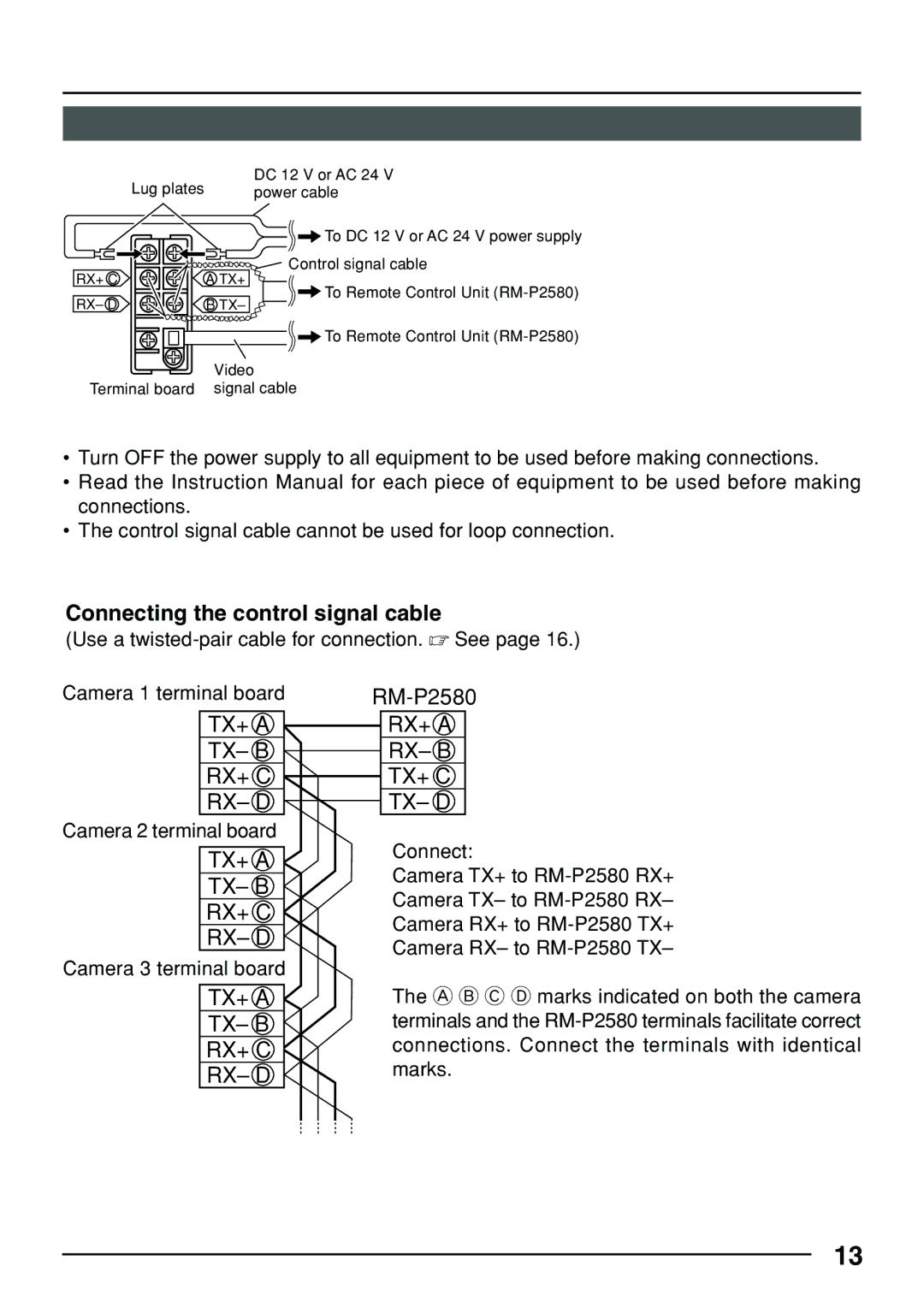
Connect:
Camera TX+ to RM-P2580 RX+ Camera TX– to RM-P2580 RX– Camera RX+ to RM-P2580 TX+ Camera RX– to RM-P2580 TX–
The A B C D marks indicated on both the camera terminals and the RM-P2580 terminals facilitate correct connections. Connect the terminals with identical marks.
13
| Lug plates |
RX+ C | A TX+ |
RX– D | B TX– |
DC 12 V or AC 24 V power cable
![]()
![]() To DC 12 V or AC 24 V power supply
To DC 12 V or AC 24 V power supply
![]() Control signal cable
Control signal cable
![]()
![]() To Remote Control Unit
To Remote Control Unit
![]()
![]() To Remote Control Unit
To Remote Control Unit
Video
Terminal board signal cable
•Turn OFF the power supply to all equipment to be used before making connections.
•Read the Instruction Manual for each piece of equipment to be used before making connections.
•The control signal cable cannot be used for loop connection.
Connecting the control signal cable
(Use a
Camera 1 terminal board
TX+ A
TX– B
RX+ C
RX– D
Camera 2 terminal board
TX+ A
TX– B
RX+ C
RX– D
Camera 3 terminal board
TX+ A
TX– B
RX+ C
RX– D