Ceiling Installation
1.
75 | Ceiling mount |
φ |
bracket
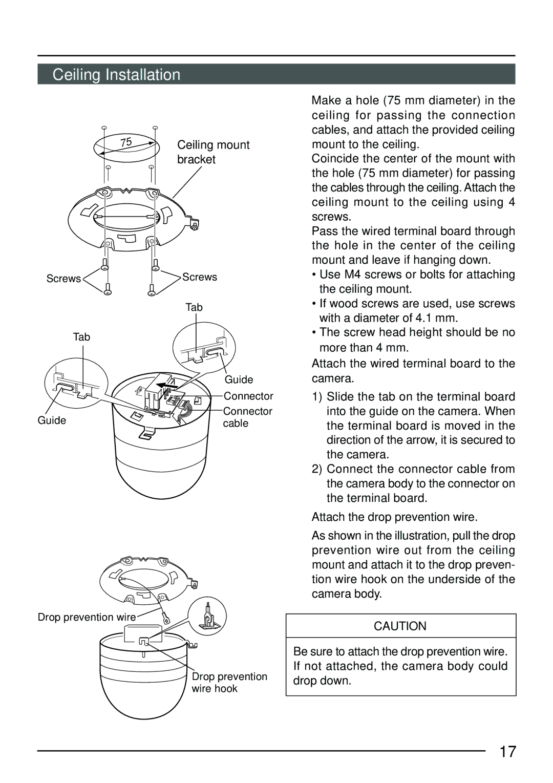
1. Make a hole (75 mm diameter) in the ceiling for passing the connection cables, and attach the provided ceiling mount to the ceiling.
Coincide the center of the mount with the hole (75 mm diameter) for passing the cables through the ceiling. Attach the ceiling mount to the ceiling using 4 screws.
Pass the wired terminal board through the hole in the center of the ceiling mount and leave if hanging down.
Screws
2.
Tab
Guide
Screws
Tab
Guide
Connector
Connector cable
• Use M4 screws or bolts for attaching |
the ceiling mount. |
• If wood screws are used, use screws |
with a diameter of 4.1 mm. |
• The screw head height should be no |
more than 4 mm. |
2. Attach the wired terminal board to the |
camera. |
1) Slide the tab on the terminal board |
into the guide on the camera. When |
the terminal board is moved in the |
direction of the arrow, it is secured to |
the camera. |
2) Connect the connector cable from |
the camera body to the connector on |
the terminal board. |
3. Attach the drop prevention wire. |
3.
Drop prevention wire
Drop prevention wire hook
As shown in the illustration, pull the drop |
prevention wire out from the ceiling |
mount and attach it to the drop preven- |
tion wire hook on the underside of the |
camera body. |
CAUTION
Be sure to attach the drop prevention wire. If not attached, the camera body could drop down.
17
