TK-260G/270G
ADJUSTMENT
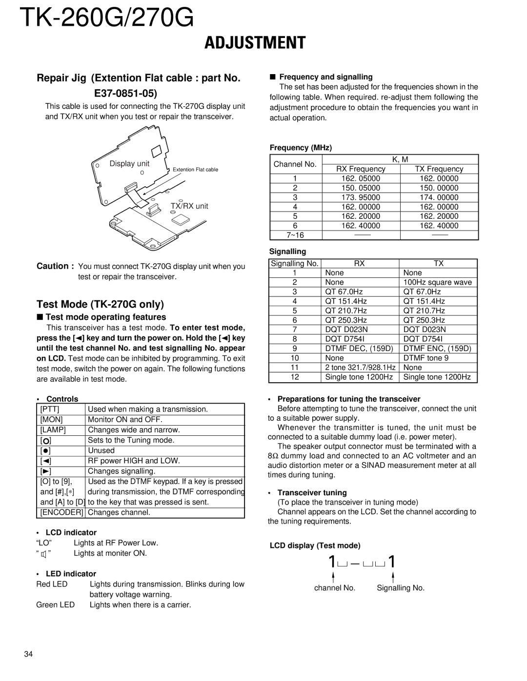
Repair Jig (Extention Flat cable : part No.
E37-0851-05)
This cable is used for connecting the
Display unit
Extention Flat cable
TX/RX unit
Caution : You must connect
Test Mode (TK-270G only)
■Test mode operating features
This transceiver has a test mode. To enter test mode, press the [2] key and turn the power on. Hold the [2] key until the test channel No. and test signalling No. appear on LCD. Test mode can be inhibited by programming. To exit test mode, switch the power on again. The following functions are available in test mode.
• Controls
[PTT] | Used when making a transmission. |
|
|
[MON] | Monitor ON and OFF. |
[LAMP] | Changes wide and narrow. |
[°] | Sets to the Tuning mode. |
[•] | Unused |
[2] | RF power HIGH and LOW. |
[3] | Changes signalling. |
[O] to [9], | Used as the DTMF keypad. If a key is pressed |
and [#],[∗] | during transmission, the DTMF corresponding |
and [A] to [D] | to the key that was pressed is sent. |
|
|
[ENCODER] | Changes channel. |
• LCD indicator
■Frequency and signalling
The set has been adjusted for the frequencies shown in the
following table. When required.
Frequency (MHz)
| Channel No. |
|
| K, M | |||
| RX Frequency | TX Frequency | |||||
|
| ||||||
| 1 | 162. 05000 | 162. 00000 | ||||
| 2 | 150. 05000 | 150. 00000 | ||||
| 3 | 173. 95000 | 174. 00000 | ||||
| 4 | 162. 00000 | 162. 00000 | ||||
| 5 | 162. 20000 | 162. 20000 | ||||
| 6 | 162. 40000 | 162. 40000 | ||||
| 7~16 |
|
|
|
|
|
|
|
|
|
|
|
|
| |
Signalling |
|
|
|
|
|
| |
|
|
|
|
| |||
| Signalling No. | RX |
| TX | |||
| 1 | None | None | ||||
| 2 | None | 100Hz square wave | ||||
| 3 | QT 67.0Hz | QT 67.0Hz | ||||
| 4 | QT 151.4Hz | QT 151.4Hz | ||||
| 5 | QT 210.7Hz | QT 210.7Hz | ||||
| 6 | QT 250.3Hz | QT 250.3Hz | ||||
| 7 | DQT D023N | DQT D023N | ||||
| 8 | DQT D754I | DQT D754I | ||||
| 9 | DTMF DEC, (159D) | DTMF ENC, (159D) | ||||
| 10 | None | DTMF tone 9 | ||||
| 11 | 2 tone 321.7/928.1Hz | None | ||||
| 12 | Single tone 1200Hz | Single tone 1200Hz | ||||
|
|
|
|
|
|
|
|
• Preparations for tuning the transceiver
Before attempting to tune the transceiver, connect the unit to a suitable power supply.
Whenever the transmitter is tuned, the unit must be connected to a suitable dummy load (i.e. power meter).
The speaker output connector must be terminated with a 8Ω dummy load and connected to an AC voltmeter and an audio distortion meter or a SINAD measurement meter at all times during tuning.
• Transceiver tuning
(To place the transceiver in tuning mode)
Channel appears on the LCD. Set the channel according to the tuning requirements.
“LO” | Lights at RF Power Low. | |
“ ” | Lights at moniter ON. | |
• LED indicator | ||
Red LED |
| Lights during transmission. Blinks during low |
|
| battery voltage warning. |
Green LED | Lights when there is a carrier. | |
LCD display (Test mode)
1![]()
![]()
![]()
![]()
![]() 1
1
channel No. | Signalling No. |
34