|
|
|
| |
|
| ADJUSTMENT | ||
Test Equipment Required for Alignment |
|
| ||
|
|
|
|
|
| Test Equipment |
| Major Specifications |
|
|
|
|
|
|
1. | Standard Signal Generator | Frequency Range | 150 to 175MHz | |
| (SSG) | Modulation | Frequency modulation and external modulation. |
|
|
| Output |
| |
2. | Power Meter | Input Impedance | 50Ω. |
|
|
| Operation Frequency | 150 to 175MHz or more. |
|
|
| Measurement Range | Vicinity of 10W |
|
3. | Deviation Meter | Frequency Range | 150 to 175MHz. |
|
|
|
|
|
|
4. | Digital Volt Meter | Measuring Range | 10mV to 10V DC |
|
| (DVM) | Input Impedance | High input impedance for minimum circuit loading. |
|
5. | Oscilloscope |
| DC through 30MHz. |
|
|
|
|
|
|
6. | High Sensitivity | Frequency Range | 10Hz to 1000MHz. |
|
| Frequency Counter | Frequency Stability | 0.2ppm or less. |
|
7. | Ammeter |
| 5A. |
|
|
|
|
|
|
8. | AF Volt Meter | Frequency Range | 50Hz to 10kHz. |
|
| (AF VTVM) | Voltage Range | 1mV to 10V. |
|
9. | Audio Generator (AG) | Frequency Range | 50Hz to 5kHz or more. |
|
|
| Output | 0 to 1V. |
|
|
|
|
|
|
10. | Distortion Meter | Capability | 3% or less at 1kHz. |
|
|
| Input Level | 50mV to 10Vrms. |
|
|
|
|
|
|
11. | Spectrum Analyzer | Measuring Range | DC to 1GHz or more |
|
|
|
|
|
|
12. | Tracking Generator | Center frequency | 50kHz to 600MHz |
|
|
| Output Voltage | 100mV or more |
|
|
|
|
|
|
13. | 8Ω Dummy Load |
| Approx. 8Ω, 3W. | |
|
|
|
|
|
14. | Regulated Power Supply |
| 5V to 10V, approx. 3A |
|
|
|
| Useful if ammeter equipped. |
|
|
|
|
|
|
■The following parts are required for adjustment
1. Antenna connector adapter
The antenna connector of this radio uses an SMA terminal. Use an antenna connector adapter [SMA(f) – BNC(f) or SMA(f) – N(f)] for adjustment. (The adapter is not provided as
an option, so buy a
Note
When the antenna connector adapter touches the knob, draw out the knob to mount the connector.
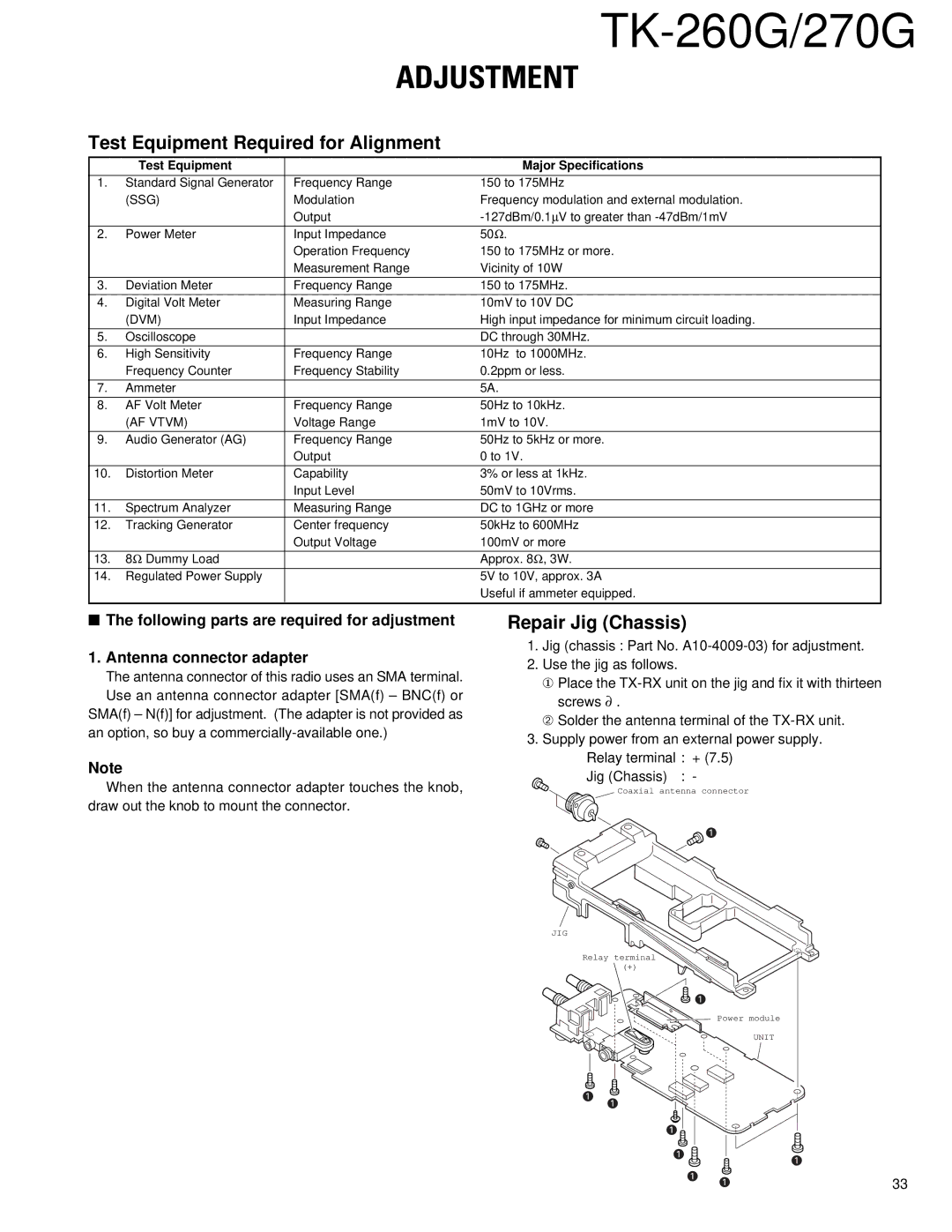
Repair Jig (Chassis)
1.Jig (chassis : Part No.
2.Use the jig as follows.
①Place the
➁Solder the antenna terminal of the
3.Supply power from an external power supply. Relay terminal : + (7.5)
Jig (Chassis) : -
Coaxial antenna connector
z
JIG
Relay terminal
(+)
![]() z
z
Power module
UNIT
z z
z |
|
z | z |
| |
z z | 33 |