TM-D700A
Features
Thank YOU
Models Covered by this Manual
When condensation occurs inside the transceiver
One or more of the following statements may be applicable
Contents
Recalling the Call Channel Reprogramming the Call Channel
Selecting the Number of Channels Using Visual Scan
Setting Scan Limits Using Program Scan
Locking Out a Memory Channel
Changing MULTI-FUNCTION
Squelch Hang Time
Supplied Accessories
Conventions Followed in this Manual
Mobile Installation
Main Unit Installation
Preparation
Front Panel Installation
Slide the front panel down until its locking tab clicks
Fixed Station Installation
Modular Plug Cable Connection
DC Power Cable Connection
Mobile Operation
Fixed Station Operation
PS-33 20.5 A, 25% duty cycle
Replacing Fuses
Transceiver 15 a Supplied Accessory 20 a DC Power Cable
Antenna Connection
Fuse Location Fuse Current Rating
Accessory Connections
External Speakers
Microphone
Your First QSO
Ew wew w
Getting Acquainted
Front Panel
3SQL control
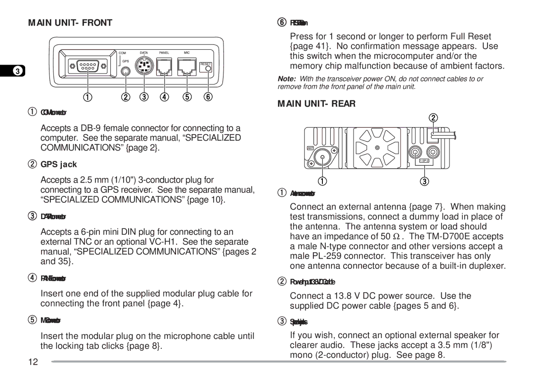
Main UNIT- Front
Main UNIT- Rear
GPS jack
Microphone
Indicators
Basic Transceiver Modes
Button Function Display
TX Band
Band a & B
TX Band and Control Band
Control Band
MIC Keypad Direct Entry MC-53DM only
Switch on the DC power supply
Switching Power ON/OFF
Adjusting Volume
Operating Basics
Adjusting Squelch
Selecting a Frequency
Selecting Output Power
When you finish speaking, release Mic PTT
Transmitting
Menu SET-UP
Menu Access
Press MNU to enter Menu mode
Press c/ d to select the appropriate level 1 No Press OK
Menu Configuration
Level Selections Default
Memory Channel Lockout
Auto PM Channel Store
Channel Display
Memory channel name See reference Number Store
Mic PF Key See reference Mic MR Key
Visual Scan Automatic Power Off APO
Remote Control
Mic VFO Key See reference
Message See reference Color for message
My call sign See reference Color for call sign
White
RSV report See reference Color for RSV report
Status text transmit rate See reference
Commander call sign See reference Transporter call sign
Sky Command mode
Packet path See reference
Operating Through Repeaters
Offset Programming Flow
Selecting Offset Frequency
Programming Offset
Selecting Offset Direction
Press c / d to select Radio 1-, then press
Press Tone to activate the Tone function
Activating Tone Function
Selecting a Tone Frequency
Press F, T.SEL
Automatic Repeater Offset
A. and Canada versions
Transmitting a 1750 Hz Tone
Press REV to switch the Reverse function on or OFF
Reverse Function
Automatic Simplex Check ASC
Tone FREQ. ID
Press Scan to activate the Tone Freq. ID
Memory Channels
Simplex & Repeater or ODD-SPLIT Memory CHANNEL?
Parameter Simplex Odd-split
Storing ODD-SPLIT Repeater Frequencies
Press M.IN 1 s
Select the desired transmit frequency Press M.IN
Recalling a Memory Channel
Select band a or B Press MR to enter Memory Recall mode
Press MHz Tuning control+ Power on
Clearing a Memory Channel
Press a
Turn the Tuning control to select the first digit
Naming a Memory Channel
Repeat steps 6 and 7 to enter up to 8 digits
Reprogramming the Call Channel
Call Channel
Recalling the Call Channel
Press VFO
MEMORY-TO-VFO Transfer
Channel Display
Band B
Partial or Full RESET?
Parameter
440.000 MHz
Programmable Memory PM
Programmable Information
Application Examples
Situationit ti
Storing in PM Channels
Recalling a PM Channel
PM Channel Reset
Press PM+ Power on
Auto PM Channel Store
Scan
Scan Type Scan Range
Visual Scan
Mode 1 31 ch
Mode 2 61 ch
Selecting the Number of Channels
Using Visual Scan
Press F, Visual to start Visual Scan
To quit Visual Scan, press ESC
Seek mode
Time-Operated mode
Carrier-Operated mode
Selecting Scan Resume Method
Press VFO 1 s
VFO Scan
Memory Scan
Select band a or B
Locking Out a Memory Channel
Press MHz Tuning control 1 s
Group Scan
To quit Group Scan, press MHz again
Setting Scan Limits
Program Scan
Select the desired frequency as the lower limit Press F
To quit Program Scan, press VFO again
Using Program Scan
Select the appropriate band
To quit MHz Scan, press MHz again
To quit Call/VFO Scan, press Call again
CALL/VFO Scan
CALL/MEMORY Scan
To quit Call/Memory Scan, press Call again
Press the left or right Band SEL to select band a or B
Using Ctcss
Continuous Tone Coded Squelch System Ctcss
Press Tone to activate the Ctcss function
Ctcss FREQ. ID
Press Scan to activate the Ctcss Freq. ID
Using DCS
Digital Code Squelch DCS
Press Tone to activate the DCS function
DCS Code ID
Press Scan to activate the DCS Code ID
Manual Dialing
Dtmf Monitor
Freq. Hz 1209 1336 1477 1633
Storing a Dtmf Number in Memory
Turn the Tuning control to select a character
Automatic Dialer
Repeat steps 4 and 5 to enter up to 8 digits
Transmitting a Stored Dtmf Number
Selecting TX Speed
Selecting Pause Duration
MR PF2
Programmable Function PF Keys
PF PF1
VFO PF3
Auxiliary Functions
Press VFO Press Mic Enter
Press the numeric keys in sequence on the keypad
Press VFO Press F, Step
Changing Frequency Step Size
Programmable VFO
Press c/ d to select the desired step size
Auto Dimmer Change Display Contrast Adjust
Display Dimmer
POSITIVE/ Negative Reversal
Blanking a Band Display
Automatic Band Change A.B.C
Transceiver Lock
PWR switch MHz SQL controls VOL controls
Press F, MHz to switch the function on or OFF
Changing MULTI-FUNCTION Button Labels
Meter Squelch
Squelch Hang Time
KEY Beep ON/ OFF
Changing Beep Volume
Switching FM/AM Mode
Advanced Intercept Point AIP
TIME-OUT Timer TOT
Automatic Power OFF APO
POWER-ON Message
Display Demonstration
Repeat steps 3 and 4 to enter up to 8 digits
Speaker Mute
Changing Speaker Configurations
Connection Mode Band a Band B
Changing TX/RX Deviation TM-D700E only
Microphone Control with MC-53DM only
Wireless Remote Control U.S.A./ Canada only
Preparation
Select the receive frequency on band B UHF
Access Menu 1-A-3 Control and select on
Control Operation
Digits Enter or VFO UP/ Down
SKY Command 2 U.S.A./ Canada only
Freq
Connecting the Transporter with the HF Transceiver
TM-D700A
Preparation Flow
17 r
Programming a Tone Frequency
On Commander
Programming Call Signs
On Transporter
Mic Key Function
RIT ON/ OFF XIT ON/ OFF
T y
Repeater Function U.S.A./ Canada only
VS-3 Voice Synthesizer Optional
Band SEL
PG-2N PG-3B PG-4X PG-5A
Optional Accessories
PS-33 SP-50B VS-3 VC-H1
MC-45 MC-53DM MC-80 MJ-88 MJ-89
Remove the 6 screws from the lower cover of the main unit
Installing Options
Installing the PG-4X Extension Cable KIT
Replace the lower cover 6 screws
Connections Using One Set of PG-4X Kit
Connections Using Two Sets of PG-4X Kits
Service Note
Maintenance
Service
Cleaning
Troubleshooting
Problem Probable Cause Corrective Action
COM Port
Specifications
VHF Band UHF Band
Transmitter
Sub VHF or UHF band
Index