Adjustments
Adjusting the PHOTOCELL
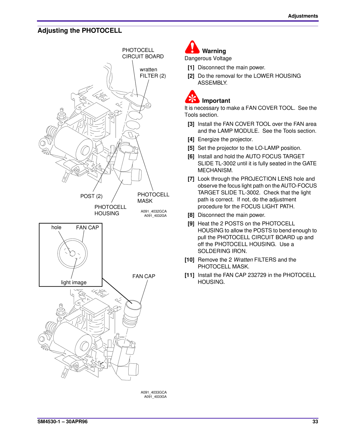
PHOTOCELL
CIRCUIT BOARD
wratten FILTER (2)
| POST (2) | PHOTOCELL |
| MASK | |
|
| |
| PHOTOCELL | A091_4032GCA |
| HOUSING | |
| A091_4032GA | |
|
| |
hole | FAN CAP |
|
FAN CAP
light image
A091_4033GCA
A091_4033GA
Warning
Dangerous Voltage
[1]Disconnect the main power.
[2]Do the removal for the LOWER HOUSING ASSEMBLY.
![]() Important
Important
It is necessary to make a FAN COVER TOOL. See the Tools section.
[3]Install the FAN COVER TOOL over the FAN area and the LAMP MODULE. See the Tools section.
[4]Energize the projector.
[5]Set the projector to the
[6]Install and hold the AUTO FOCUS TARGET SLIDE
[7]Look through the PROJECTION LENS hole and observe the focus light path on the
[8]Disconnect the main power.
[9]Heat the 2 POSTS on the PHOTOCELL HOUSING to allow the POSTS to bend enough to pull the PHOTOCELL CIRCUIT BOARD up and off the PHOTOCELL HOUSING. Use a
SOLDERING IRON.
[10]Remove the 2 Wratten FILTERS and the
PHOTOCELL MASK.
[11]Install the FAN CAP 232729 in the PHOTOCELL HOUSING.
33 |