SERVICE MANUAL
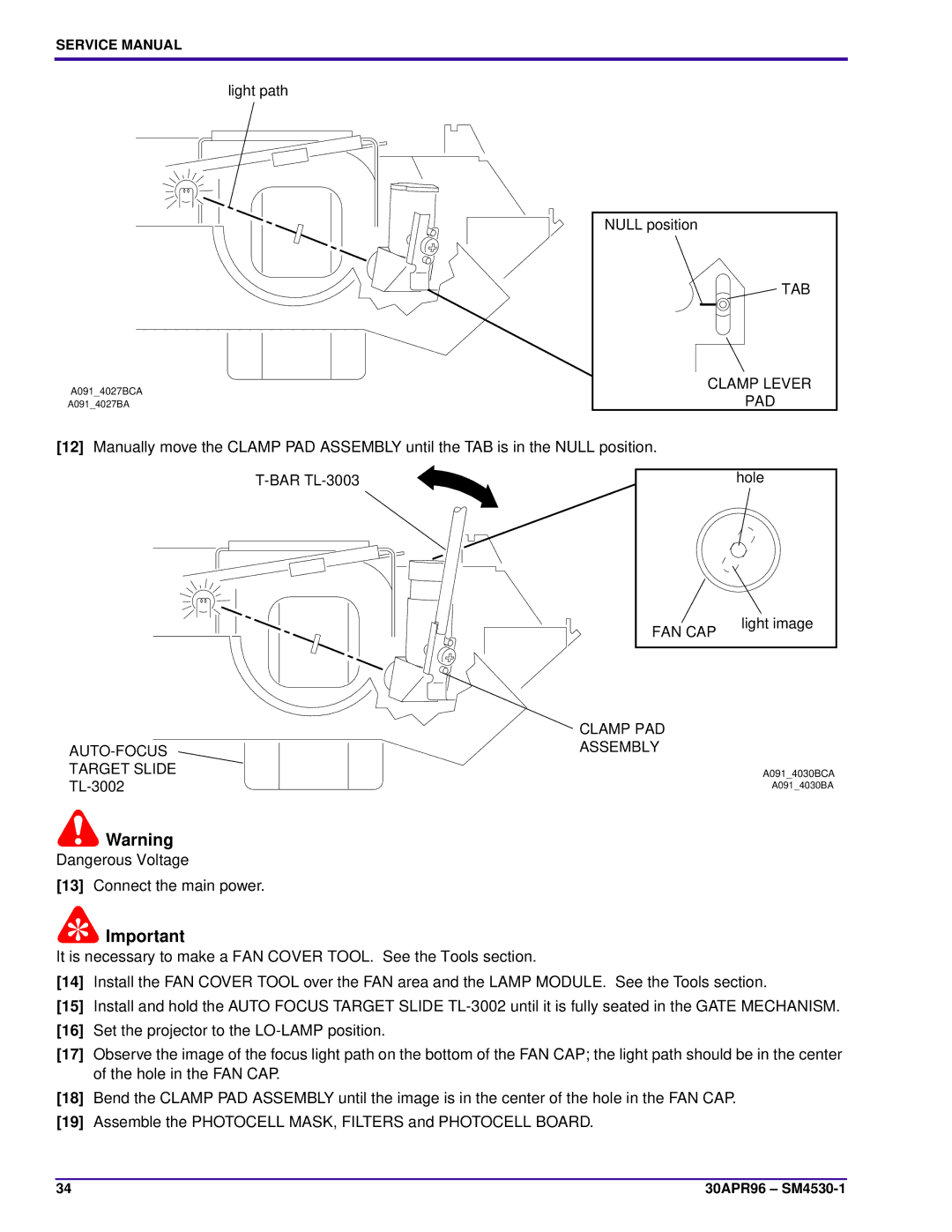
light path
NULL position
TAB
A091_4027BCA | CLAMP LEVER | |
PAD | ||
A091_4027BA |
[12]Manually move the CLAMP PAD ASSEMBLY until the TAB is in the NULL position.
hole |
FAN CAP
light image
| CLAMP PAD |
| ASSEMBLY |
TARGET SLIDE | A091_4030BCA |
A091_4030BA |
![]() Warning
Warning
Dangerous Voltage
[13]Connect the main power.
![]() Important
Important
It is necessary to make a FAN COVER TOOL. See the Tools section.
[14]Install the FAN COVER TOOL over the FAN area and the LAMP MODULE. See the Tools section.
[15]Install and hold the AUTO FOCUS TARGET SLIDE
[16]Set the projector to the
[17]Observe the image of the focus light path on the bottom of the FAN CAP; the light path should be in the center of the hole in the FAN CAP.
[18]Bend the CLAMP PAD ASSEMBLY until the image is in the center of the hole in the FAN CAP.
[19]Assemble the PHOTOCELL MASK, FILTERS and PHOTOCELL BOARD.
34 | 30APR96 – |