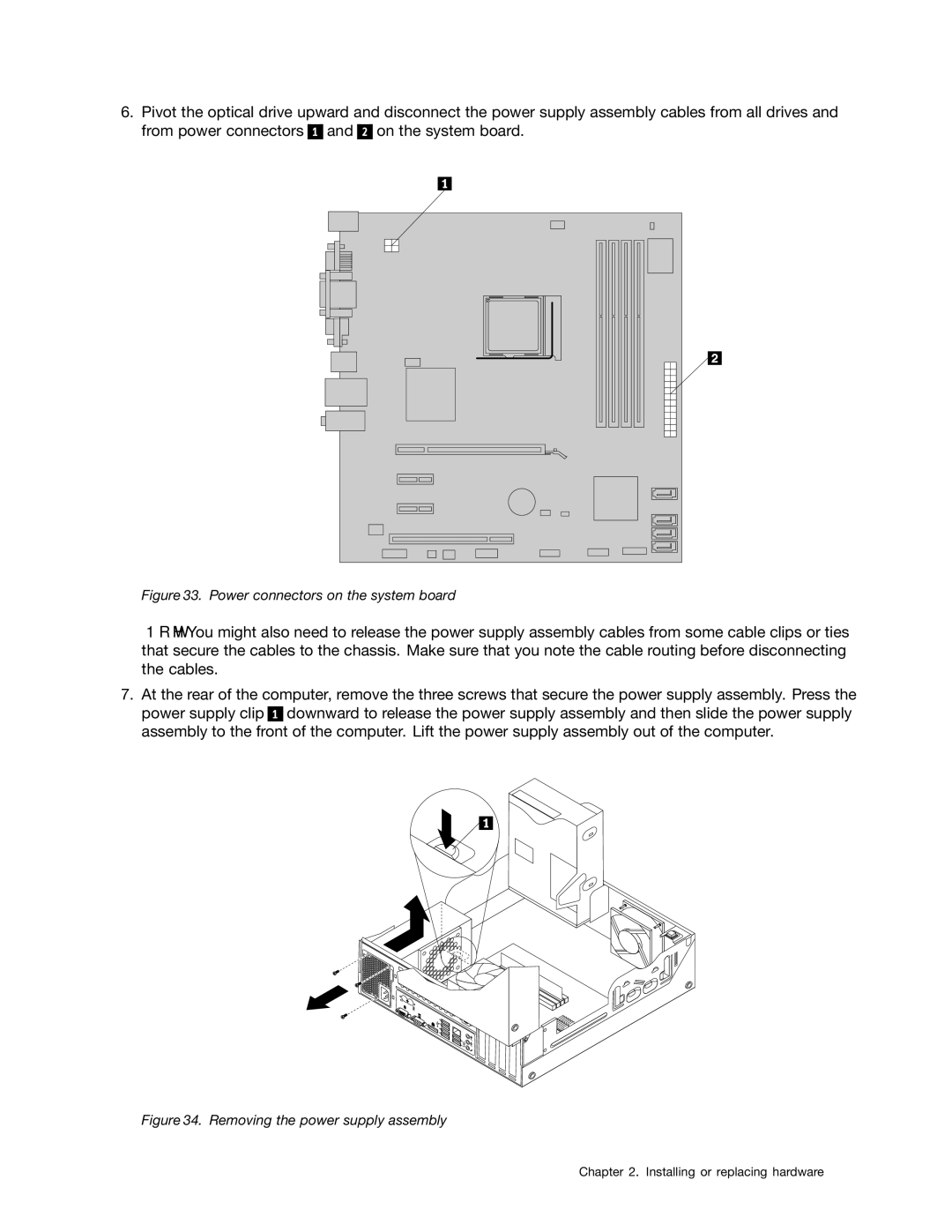
6.Pivot the optical drive upward and disconnect the power supply assembly cables from all drives and from power connectors 1 and 2 on the system board.
Figure 33. Power connectors on the system board
Note: You might also need to release the power supply assembly cables from some cable clips or ties that secure the cables to the chassis. Make sure that you note the cable routing before disconnecting the cables.
7.At the rear of the computer, remove the three screws that secure the power supply assembly. Press the power supply clip 1 downward to release the power supply assembly and then slide the power supply assembly to the front of the computer. Lift the power supply assembly out of the computer.