MC-12Digital Controller
Important Safety Instructions
Customer Support
Introduction
Getting Started
Important Safety Instructions
Basic Operation
Unpacking and Inspection
Mode Adjust
Setup
Troubleshooting & Maintenance
Audio Controls
English Important Safety Instructions
Español Instrucciones DE Seguridad Importantes
Vii
Viii
Norsk Viktig Informasjon OM Sikkerhet
DE Auspacken und Überprüfung
US Unpacking and Inspection
ES Desembalaje e inspección
FR Contenu de l’emballage et inspection
Getting Started
About the MC-12
Getting Started
Highlights
Product Registration Installation Considerations
Do not
Do not
To replace the remote control batteries
Remote Control Battery Installation
Basic Operation
Standby Button
Front Panel Overview
Volume Knob
Mode & Buttons
Front Panel Display
IR Receiver
To use the volume knob to adjust Main Zone volume level
Main Zone Off Button
Main Zone Input Selection Buttons
Zone 2 Input Selection Buttons
Zone 2 Off Button
Main Outputs
Rear Panel Overview
AC Input Connector
Power Switch
Digital Audio Input Connectors S/PDIF & AES/EBU
Analog Audio Input Connectors
Rear Panel Overview from
Balanced Audio Output Connectors MC-12 Balanced
Record Zone Audio Output Connectors
Video Input Connectors
Main Zone Video Output Connectors
IR in Connector
Trigger Output Connectors
Microphone Input Connectors
Removable Access Panel
Button Navigation Commands
Main Menu
Menu Navigation
Menu Item Selection
To select the desired setting on a parameter drop-down menu
Options
Parameters
Command Matrix
Command Bank Activation
To select a parameter setting with a horizontal graph
To activate a command bank
Main Zone Record Zone
Button
Button Main Zone Record Zone Shift
Screen Display
Main Menu
Digital
TWO-LINE Status
Understanding the Zones
Main Zone Two-Line Status
Zone 2 Two-Line Status
Record Zone Two-Line Status
Status Menus
Two-Line Status from
Parameter Possible Settings
2CH Status
Refer to page 2-24 for status menu parameter descriptions
Status
1a Bypass Status
Analog Status
2CH Bypass Status
Digital Status
BIT Rate
Encoding
Center MIX LVL
Channels
Input Type
Input
MIX Room
Mode
Setup
Volume Controls
Rear Panel Config
Displays
Inputs
Lock Options
Input Setup
Changing Input Names
Edit Input Name
To customize the name of the selected input
To restore the factory-default name of the selected input
Restore Default Name
Component
Assigning Audio & Video Input Connectors
Analog
Assigning Audio & Video Input Connectors continues on
Assigning Audio & Video Input Connectors from
This parameter cannot be adjusted
Anlg in LVL
Manual
Auto
Auto Gain
Level Meters
Component
Video
Preferred Listening Mode Selection Parameters
Selecting Preferred Listening Modes
Selecting Preferred Listening Modes continues on
Selecting Preferred Listening Modes from
Setup Inputs DVD1 @*D
Main Advanced
Configuring Advanced Input Settings
Input Select
Configuring Advanced Input Settings continues on
Analog Bypass
Video
Input Select Parameter Settings
Configuring Advanced Input Settings from
Component OSD
Video OSD
Anlg Analog Dmix Downmix
ZONE2 & Record in Parameter Settings
Record Advanced
Record
Digital Bypass
Speaker Setup
Setting Crossover Points
Setting Crossover Points continues on
Custom Speaker Setups
To configure a custom speaker setup
Setting Crossover Points from
Highpass Filter
When the THX Speaker Setup screen opens
THX Speaker Setups
Custom Setup Menu THX Setup Menu
Speaker Setup Parameters
Parameter Default Setting Possible Settings
These parameters cannot be adjusted on the THX Setup menu
Front L/R
Side L/R
Center
Rear L/R
SUB Xover
SUB L/R
LFE
When a custom speaker setup is selected
BGC Boundary Gain Compensation
ULTRA2 SUB
ASA Advanced Speaker Array
ASA Advanced Speaker Array continues on
Calibrating Speaker Distances & Output Levels
ASA Advanced Speaker Array from
Speaker Calibration Parameters
Speaker Distance Parameters
Units
Speaker Distance Settings Output Level Settings
Automatic Options Details
Automatic Calibration
Microphone Inputs
Step a Connecting the Microphones
During the microphone check, position the microphones
Step B Positioning the Microphones for the Microphone Check
During the microphone check, do not
Checking for Silence
Step C Checking the Microphones
Step C Checking the Microphones continues on
Check Microphones Results
Step C Checking the Microphones from
Message Description Troubleshooting
Setup
Setup
Setup
During automatic calibration, do not
Setup
Step E Performing Automatic Calibration
Distances
Levels
Step E Performing Automatic Calibration continues on
Step Distances Distances & Levels
Front Left
Step E Performing Automatic Calibration from
Configure Bass Peak Limiters menu parameter settings
Auto Speaker Setup results screen shown above
MC-12 calibrated the value for
Manual Options Details
Manual Calibration
To manually calibrate speaker distances
Performing Manual Speaker Distance Calibration
Performing Manual Output Level Calibration continues on
Performing Manual Output Level Calibration
When the Internal Noise message opens
Internal Noise Test
From
External Noise Test
Input Source Listening Mode
Parameter Default Possible Setting Settings
Setting Bass Peak Limiters
Limiter
CAL Noise
Limit ADJ
LFE Limiter
When 5 Stereo & 5.1 Anlg is selected
Rear Panel Config
When 8 Stereo Inputs is selected
Stereo & 5.1 Anlg
Sync Delay
Display Setup
Default Possible Parameter Setting Settings
Display Setup continues on
Display Setup from
Edit Custom Name
To create a custom unit name
ON-SCREEN Display
Status
On-Screen Display continues on
Position
Letter Indicator Command Bank
Format
Background
Brightness
Front Panel Display
Main PWR on
Volume Control Setup
Mute Level
Zone PWR on
Trigger Setup
Trigger Setup from
Remote only
Lock Options
Setup
Modes
Audio Cntrl
Audio Controls
Audio Controls menu parameter descriptions begin on the next
Audio Controls
Bass
Treble
When the Shift command bank is activated
Tilt EQ
Loudness
Loudness
Fader
Balance
ZONE2 Balance
Record Balance
Mode Adjust
Mode Adjust
Listening Mode Activation
Listening mode activation occurs through
Preferred Listening Mode Selection Parameters
Mode Family Selection Buttons
Mode Buttons
Channel Dolby Digital Dts-ES Channel Analog
Button Input Source
Listening Mode Descriptions
Listening mode menu parameter descriptions begin on
Film
Music
Plii +
Music Surr
Plii Music
Plii Movie
Film & Music
PRO Logic
Concert Hall
Nightclub
Cathedral
Church
Calibration
Panorama
To calibrate the Panorama listening mode
Mode Adjust
CH Surround
Channel
Mono Logic
Mono Surround
Mono
Film
Music
ULTRA2, 5.1 SurEX
Parameter Setting
Channel
Dolby Digital Flagged Dolby Digital Non-Flagged
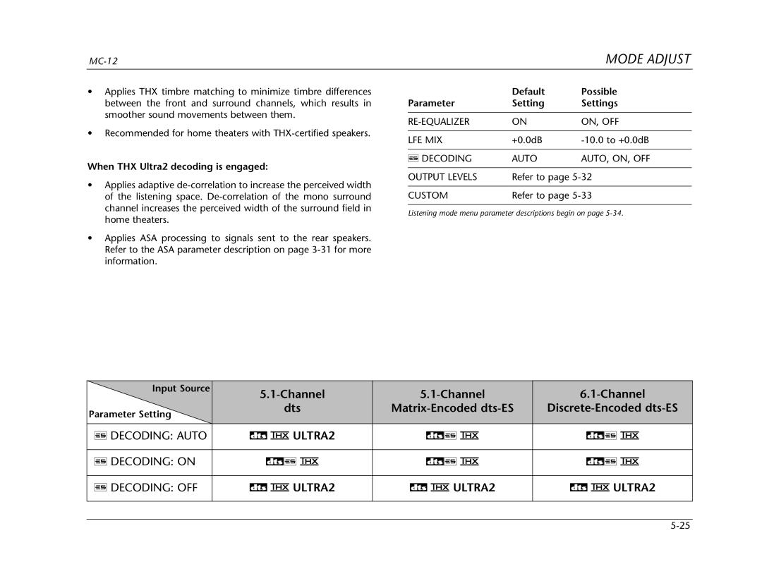
When THX Ultra2 decoding is engaged
When THX Surround EX decoding is engaged
ULTRA2, 5.1 SurEX
Digital EX & Digital continues on
Digital EX & Digital
EX Decoding Auto
Flagged Non-Flagged
2-CHANNEL
Mono Surr
Mono
Decoding
Decoding Auto
ULTRA2
Decoding Auto ULTRA2 Decoding on
Dts
Mode Adjust @@ @** Music
1a Film
Chan
1a ULTRA2, 5.1a SurEX, & 5.1a
1a Music
Analog Flagged Analog Non-Flagged
Parameter Setting Settings
Surround EX on
SurEX
1a Standard
1a Bypass
1a 2-CHANNEL
Output Levels
2CH Bypass
Reset Mode
Custom VS Preset
Reset Mode continues on
Custom
Bass Content
Listening Mode Menu Parameter Descriptions
Spkr Enhance
Academy Filter
Bass RT
Bass Enhance
Center Depth
Center MIX
CTR Width
Dimension
Custom
Effect LVL
Input Balance
EX Decoding
Listener POS
LFE MIX
Liveness
LOW Freq Width
Output Levels
PRE-DELAY
Panorama
RE-EQUALIZER
Sound Stage
Size
Source
Speaker Angle
Surr Rolloff
Surround DLY
Surround EX
Vocal Enhance
Surround MIX
Troubleshooting & Maintenance
MC-12 does not power on
Troubleshooting
Remote control does not work
MC-12 is powered on, but there is no audio
RF interference is present in the audio or video signal
MC-12 is powered on, but there is no video
Humming sound is present in the audio
MC-12 is exhibiting erratic behavior
Routine Maintenance
Restoring FACTORY-DEFAULT Settings
To restore factory-default settings
Troubleshooting & Maintenance
Appendix
Specifications are subject to change without notice
Specifications
Audio Input & Output Connectors
Main Zone Audio Performance
Microphone Input Connectors
Video Input & Output Connectors
Specifications continues on page A-4
Composite & S-video Performance
Declaration of Conformity
Appendix
Menu Trees from page A-5
Parameter settings for each input
Selecting an Input Setup menu item opens
Menu Trees from page A-7
Main Menu Setup Speaker Setup
Microphones
Menu Trees from page A-9
Press V to Skip Countdown Setting Distances Front Left
Menu Trees from page A-11
Meters
Menu Trees from page A-14
CH Surround Output Levels Custom Channel SUB L/R LVL
Menu Trees from page A-15
Input Balance LFE MIX
Menu Trees from page A-17
Input Setup DVD1 DVD2 SAT VCR PVR Game Tape Tuner AUX
Installation Worksheet
Installation Worksheet from page A-19
Custom Setup THX Setup Speaker Distances Levels Calibration
Display Setup Trigger 1 Setup Trigger 2 Setup
Index continues on
Menu ill
Ill
Calibration
Audio
About the, 1-2 to
12ill
Parameters
30ill., A-9ill
Ill., A-9ill., A-20
Page
Page
Limited Warranty
Product Registration LEXICON, INC 3 OAK Park Bedford MA