Extension Cord
If an extension cord is required, use one that is rated for the application and is 3 conductor #14 AWG (2.1 mm2) or larger. The recommended maximum lengths are 25 ft (7.5 m) if #14 AWG (2.1 mm2) is used and 50 ft (15 m) if #12 AWG* (3.3 mm2) is used.
*AMERICAN WIRE GAUGE
SHIELDING GAS
When using the GMAW process, a cylinder of carbon dioxide (CO2) or
The Lincoln K463 CO2 or K499
Weld shielding gas may be obtained from a welding supply distributor.
![]() WARNING
WARNING
CYLINDER may explode if damaged.
• Keep cylinder upright and chained to
support.
• Keep cylinder away from areas where it may be damaged.
•Never lift welder with cylinder attached.
•Never allow welding electrode to touch cylinder.
•Keep cylinder away from welding or other live elec-
trical circuits.
BUILDUP OF SHIELDING GAS may harm health or kill.
![]()
![]()
![]()
![]()
![]() • Shut off shielding gas supply when not
• Shut off shielding gas supply when not ![]()
![]()
![]()
![]() in use.
in use.
SEE AMERICAN NATIONAL STANDARD
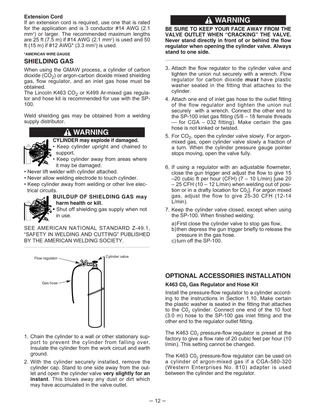
Flow regulator | Cylinder valve |
| |
Gas hose |
|
1.Chain the cylinder to a wall or other stationary sup- port to prevent the cylinder from falling over. Insulate the cylinder from the work circuit and earth ground.
2.With the cylinder securely installed, remove the cylinder cap. Stand to one side away from the out- let and open the cylinder valve very slightly for an instant. This blows away any dust or dirt which may have accumulated in the valve outlet.
![]() WARNING
WARNING
BE SURE TO KEEP YOUR FACE AWAY FROM THE VALVE OUTLET WHEN “CRACKING” THE VALVE. Never stand directly in front of or behind the flow regulator when opening the cylinder valve. Always stand to one side.
3.Attach the flow regulator to the cylinder valve and
tighten the union nut securely with a wrench. Flow regulator for carbon dioxide must have plastic washer seated in the fitting that attaches to the cylinder.
4.Attach one end of inlet gas hose to the outlet fitting of the flow regulator and tighten the union nut securely with a wrench. Connect the other end to the
— for CGA – 032 fitting). Make certain the gas hose is not kinked or twisted.
5.For CO2, open the cylinder valve slowly. For argon- mixed gas, open cylinder valve slowly a fraction of a turn. When the cylinder pressure gauge pointer stops moving, open the valve fully.
6.If using a regulator with an adjustable flowmeter, close the gun trigger and adjust the flow to give 15
– 25 CFH (10 – 12 L/min) when welding out of posi-
tion or in a drafty location for C02]. For argon mixed gas, adjust the flow to give
7.Keep the cylinder valve closed, except when using the
a)First close the cylinder valve to stop gas flow, b)then depress the gun trigger briefly to release the
pressure in the gas hose. c) turn off the
OPTIONAL ACCESSORIES INSTALLATION
K463 C02 Gas Regulator and Hose Kit
Install the
The K463 C02
The K463 C02
acylinder of
– 12 –