Return to Section TOC
Return to Section TOC
Return to Section TOC
Return to Master TOC
Return to Master TOC
Return to Master TOC
TROUBLESHOOTING AND REPAIR | ||
|
|
CONTROL PC BOARD REMOVAL AND REPLACEMENT PROCEDURE
(Continued)
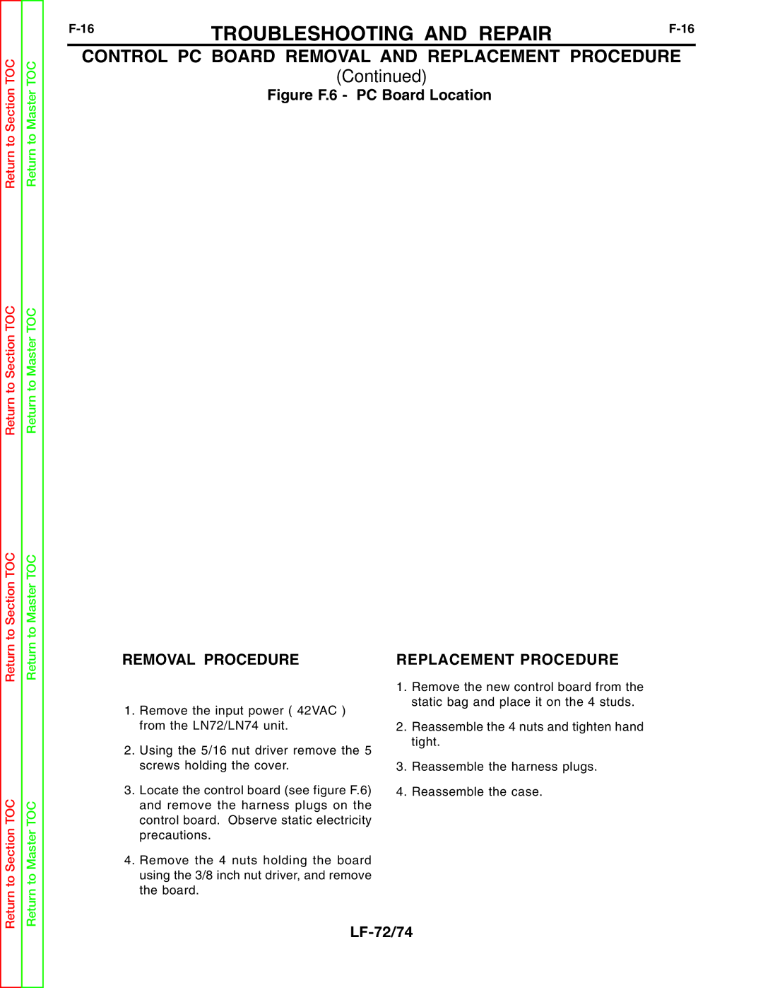
Figure F.6 - PC Board Location
CONTROL BOARD
REMOVAL PROCEDURE | REPLACEMENT PROCEDURE |
Return to Section TOC
Return to Master TOC
1.Remove the input power ( 42VAC ) from the LN72/LN74 unit.
2.Using the 5/16 nut driver remove the 5 screws holding the cover.
3.Locate the control board (see figure F.6) and remove the harness plugs on the control board. Observe static electricity precautions.
4.Remove the 4 nuts holding the board using the 3/8 inch nut driver, and remove the board.
1.Remove the new control board from the static bag and place it on the 4 studs.
2.Reassemble the 4 nuts and tighten hand tight.
3.Reassemble the harness plugs.
4.Reassemble the case.