Return to Section TOC
Return to Section TOC
Return to Section TOC
Return to Section TOC
Return to Master TOC
Return to Master TOC
Return to Master TOC
Return to Master TOC
| INSTALLATION | |
|
|
|
PRESSURE ARM ADJUSTMENT
WARNING
ELECTRIC SHOCK can kill.
•Turn the input power OFF at the welding power source before installation or changing drive rolls and/or guides.
•Do not touch electrically live parts.
•When inching with the gun trigger, electrode and drive mechanism are "hot" to work and ground and could remain energized several seconds after the gun trigger is released.
•Only qualified personnel should perform mainte- nance work.
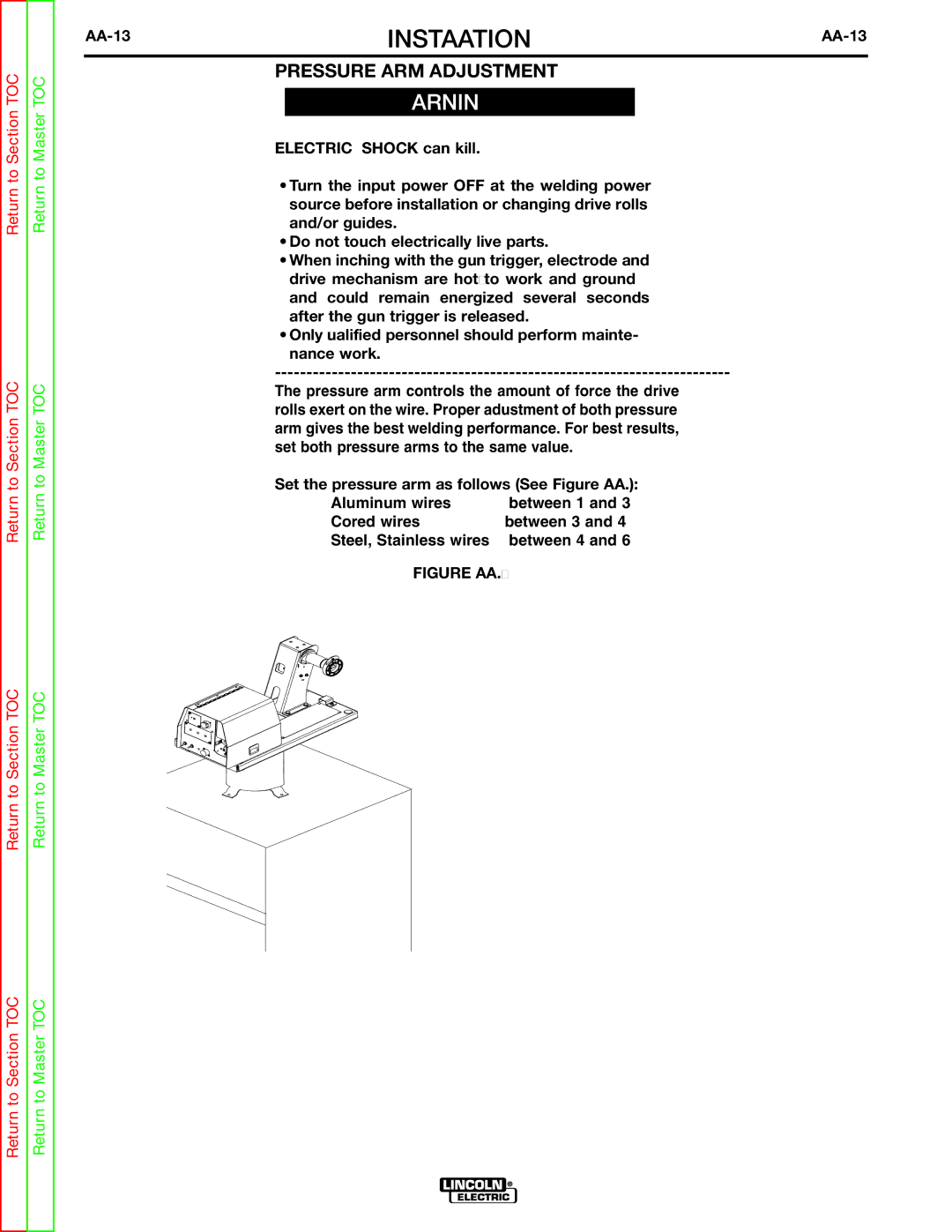
The pressure arm controls the amount of force the drive rolls exert on the wire. Proper adjustment of both pressure arm gives the best welding performance. For best results, set both pressure arms to the same value.
Set the pressure arm as follows (See Figure AA.8):
Aluminum wires | between 1 and 3 |
Cored wires | between 3 and 4 |
Steel, Stainless wires | between 4 and 6 |
FIGURE AA.8
CORED WIRES | 1 |
| SOLID WIRES |
OUTERSHIELD | 6 | ALUMINUM | |
METALSHIELD | 5 |
| |
3 | 2 | STAINLESTEELSS | |
INNERSHIELD | 4 |