Return to Section TOC
Return to Section TOC
Return to Section TOC
Return to Section TOC
Return to Master TOC
Return to Master TOC
Return to Master TOC
Return to Master TOC
OPERATION | ||
|
|
|
FRONT PANEL CONTROLS AND CONNECTIONS
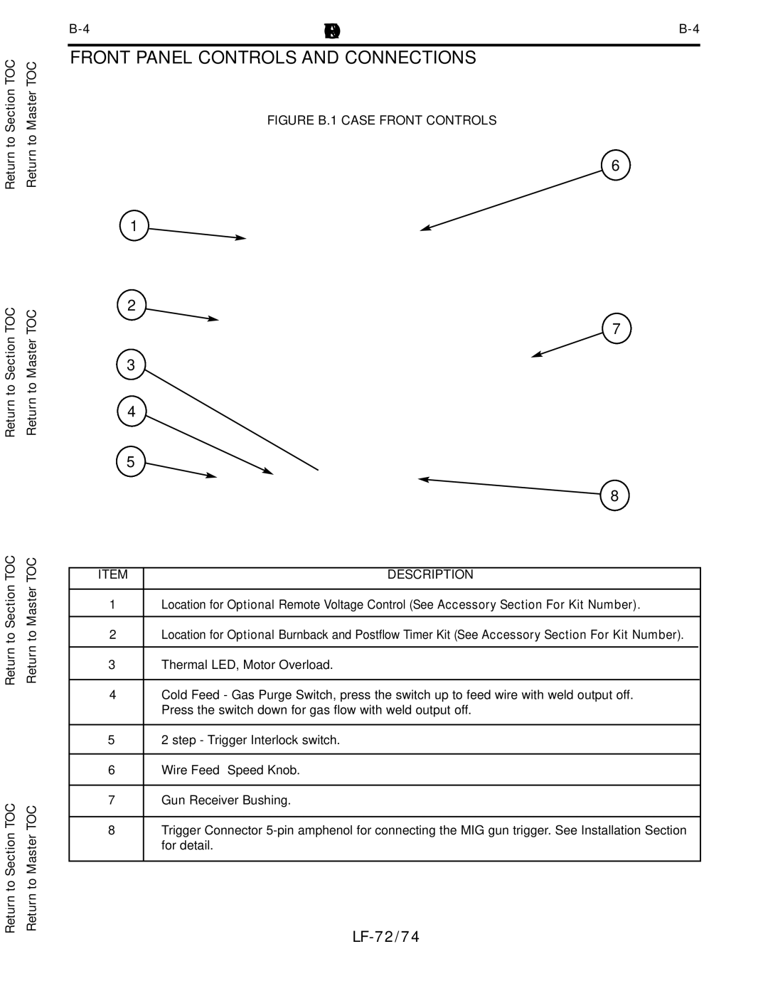
FIGURE B.1 CASE FRONT CONTROLS
6
1
2
7
3
4
5
8
ITEM | DESCRIPTION | |
|
|
|
1 | Location for Optional Remote Voltage Control (See Accessory Section For Kit Number). | |
|
|
|
2 | Location for Optional Burnback and Postflow Timer Kit (See Accessory Section For Kit Number). | |
|
|
|
3 | Thermal LED, Motor Overload. | |
|
| |
4 | Cold Feed - Gas Purge Switch, press the switch up to feed wire with weld output off. | |
| Press the switch down for gas flow with weld output off. | |
|
| |
5 | 2 step - Trigger Interlock switch. | |
|
| |
6 | Wire Feed Speed Knob. | |
|
| |
7 | Gun Receiver Bushing. | |
|
| |
8 | Trigger Connector | |
| for detail. | |
|
|
|