THEORY OF OPERATION | ||
|
|
|
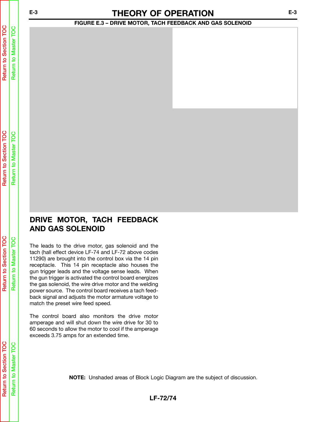
| FIGURE E.3 – DRIVE MOTOR, TACH FEEDBACK AND GAS SOLENOID |
|
Return to Master TOC
OPTIONAL BURNBACK TIMER
OPTIONAL REMOTE VOLTAGE CONTROL
| GAS |
3.75 AMP | SOLENOID |
OVERLOAD | WIRE |
PROTECTION | |
| DRIVE |
WIRE DRIVE | MOTOR |
TACK | |
RECEPTACLE | To Gun Trigger |
|
Return to Master TOC
14PIN
INPUT CABLE RECEPTACLE
24/42 VAC
CONTROL BOARD |
|
| GAS PURGE |
|
|
| COLD FEED |
|
|
|
|
|
|
|
|
|
|
|
WIRE FEED |
| TRIGGER |
| INTERLOCK | |
SPEED POT. |
|
Return to Section TOC
Return to Section TOC
Return to Section TOC
Return to Section TOC
Return to Master TOC
Return to Master TOC
DRIVE MOTOR, TACH FEEDBACK
AND GAS SOLENOID
The leads to the drive motor, gas solenoid and the tach (hall effect device
The control board also monitors the drive motor amperage and will shut down the wire drive for 30 to 60 seconds to allow the motor to cool if the amperage exceeds 3.75 amps for an extended time.
NOTE: Unshaded areas of Block Logic Diagram are the subject of discussion.