TOC
TOC
THEORY OF OPERATION |
FIGURE E.2
GENERAL DESCRIPTION & INPUT RECEPTACLE, CONTROL BOARD AND OPERATOR CONTROLS
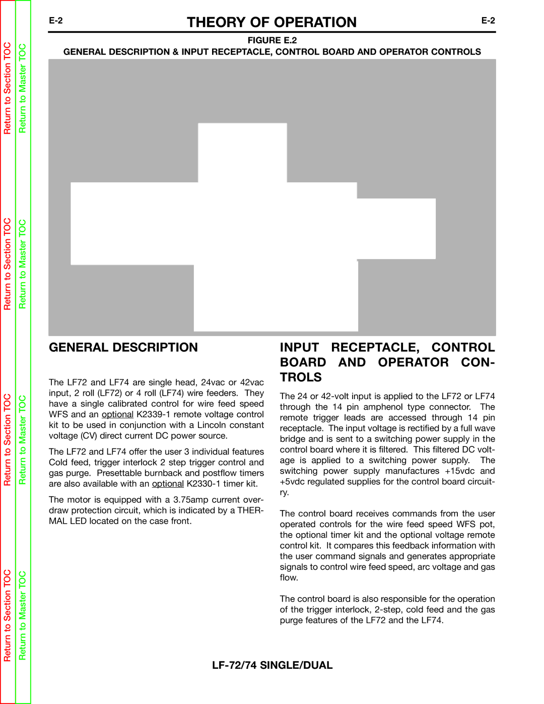
OPTIONAL BURNBACK TIMER
OPTIONAL REMOTE VOLTAGE CONTROL
| GAS |
3.75 AMP | SOLENOID |
OVERLOAD | WIRE |
PROTECTION | |
| DRIVE |
WIRE DRIVE | MOTOR |
TACK | |
RECEPTACLE | To Gun Trigger |
|
Return to Section TOC
Return to Master TOC
14PIN
INPUT CABLE RECEPTACLE
24/42 VAC
CONTROL BOARD
|
|
|
|
|
| WIRE FEED |
| TRIGGER |
|
|
| INTERLOCK |
| |
| SPEED POT. |
|
| |
|
|
|
|
|
COLD FEED GAS PURGE
Return to Section TOC
Return to Section TOC
Return to Master TOC
Return to Master TOC
GENERAL DESCRIPTION
The LF72 and LF74 are single head, 24vac or 42vac input, 2 roll (LF72) or 4 roll (LF74) wire feeders. They have a single calibrated control for wire feed speed WFS and an optional
The LF72 and LF74 offer the user 3 individual features Cold feed, trigger interlock 2 step trigger control and gas purge. Presettable burnback and postflow timers are also available with an optional
The motor is equipped with a 3.75amp current over- draw protection circuit, which is indicated by a THER- MAL LED located on the case front.
INPUT RECEPTACLE, CONTROL BOARD AND OPERATOR CON- TROLS
The 24 or
The control board receives commands from the user operated controls for the wire feed speed WFS pot, the optional timer kit and the optional voltage remote control kit. It compares this feedback information with the user command signals and generates appropriate signals to control wire feed speed, arc voltage and gas flow.
The control board is also responsible for the operation of the trigger interlock,