Return to Section TOC
Return to Section TOC
Return to Section TOC
Return to Section TOC
Return to Master TOC
Return to Master TOC
Return to Master TOC
Return to Master TOC
ELECTRICAL DIAGRAMS |
|
|
| ||
SCHEMATIC - ENTIRE MACHINE - CODE 11195, 11196, 11197, (G4942) |
|
|
|
| |
| Values for CV300. Others |
|
| ||
| may be different. |
|
|
| |
| 0 VDC @ 0 = 5.8 Arc Volts |
|
| ||
| 6.6 VDC @ 10 = 40 ArcVolts |
|
| ||
| 75A | 1 | 75 | REMOTE | Located on |
| CONTROL | ||||
|
|
|
| ||
| 76A | 2 | 76 | 10K/2W VOLTAGE | Case Front |
| 77A | 3 | 77 | POTENTIOMETER |
|
| (OPTIONAL) |
| |||
|
|
|
|
| |
| Connector located | 4 |
|
|
|
| behind case front |
|
|
|
|
| 284 pulses/sec @ 100 IPM | P7 |
|
|
|
| 1139 pulses/sec @ 400 IPM |
|
|
|
|
|
|
|
|
|
|
|
|
|
|
|
|
|
|
|
|
|
|
|
|
|
|
|
|
|
|
|
|
|
|
|
|
|
|
|
|
|
|
| 577 |
|
|
|
|
|
| WIRE FEED | Located on |
|
|
|
|
| |
|
|
|
|
|
|
|
|
|
|
|
|
|
|
|
|
|
|
|
|
|
|
|
|
|
|
|
|
|
|
|
|
|
|
|
|
|
|
| 576 |
|
|
|
|
| 10K/2W |
|
|
|
|
| |||
|
|
|
|
|
|
|
|
|
|
|
|
|
|
|
|
|
|
|
|
|
|
|
|
|
|
|
|
|
|
|
|
|
|
|
|
|
|
|
|
|
|
|
| SPEED |
|
|
|
|
| ||||
|
|
|
|
|
|
|
|
|
|
|
|
|
|
|
|
|
|
|
|
|
|
|
|
|
|
|
|
|
|
|
|
|
|
|
|
|
|
| 575 |
|
|
|
|
|
| Case Front |
|
|
|
|
| ||
|
|
|
|
|
|
|
|
|
|
|
|
|
|
|
|
|
|
|
|
|
|
|
|
|
| Connector located |
|
| Gearbox ratio is 2:47 |
|
|
|
|
|
|
|
|
|
|
|
| CONTROL |
|
|
|
|
| ||||||
|
|
|
|
|
|
|
|
|
|
|
|
|
|
|
|
|
|
|
|
|
|
|
|
|
|
|
| Motor resistance |
|
|
|
|
|
|
|
|
|
|
|
|
|
|
| ||||||||||
|
|
|
|
|
|
|
|
|
|
|
|
|
|
|
|
|
|
|
|
|
|
|
|
|
| by sheet panel |
|
| Motor is at electrode |
|
|
| 0 VDC MIN. WFS |
| POTENTIOMETER |
|
|
|
|
|
| ||||||||||||
|
|
|
|
|
|
|
|
|
|
|
|
|
|
|
|
|
|
|
|
|
|
|
|
|
|
|
| is 1.5 ohms |
|
|
|
|
|
|
|
|
|
|
| ||||||||||||||
|
|
|
|
|
|
|
|
|
|
|
|
|
|
|
|
|
|
|
|
| Leads Pass through |
|
|
|
| potential |
|
|
|
|
|
|
|
|
|
|
|
|
|
|
| ||||||||||||
|
|
|
|
|
|
|
|
|
|
|
|
|
|
|
|
|
|
|
|
|
|
|
| 1 |
|
| Motor is located |
|
|
|
|
|
|
|
| 5 VDC MIN. WFS |
|
|
|
|
|
|
|
|
| ||||||||
|
|
|
|
|
|
|
|
|
| 575 |
|
|
|
|
|
|
|
|
|
|
|
|
|
|
|
|
|
|
|
|
|
|
|
|
|
|
|
|
|
|
|
|
| ||||||||||
|
|
|
|
|
|
|
|
|
|
|
|
|
|
|
|
|
|
|
| toroid 2 times. |
|
|
|
|
|
|
|
|
|
|
|
|
|
|
|
|
|
|
|
|
|
|
|
|
|
|
|
|
| ||||
|
| Off = 0 VDC |
|
|
|
|
|
|
|
|
|
|
|
|
|
|
|
|
|
|
|
|
|
|
| R |
|
|
|
|
|
|
|
|
|
|
|
|
|
|
|
|
|
|
|
|
|
| |||||
|
|
|
|
|
|
|
|
|
|
|
|
|
|
|
|
|
|
|
| L4 |
|
| 2 |
| 40 pole | behind |
|
|
|
|
|
|
|
|
|
|
|
|
|
|
|
|
|
|
|
|
| ||||||
|
|
|
|
|
|
|
|
|
|
|
|
|
|
|
|
|
|
|
|
|
|
|
|
|
|
|
|
|
|
|
|
|
|
|
|
|
|
|
|
|
|
|
|
|
| ||||||||
|
| OCV = 59 VDC |
|
|
|
|
|
|
|
|
| 575B |
|
|
|
|
|
|
|
|
|
| 563 | 3 |
| U | ring | glastic panel |
|
|
|
|
|
|
|
|
|
|
|
|
|
|
|
|
|
|
|
|
| ||||
|
|
|
|
|
|
|
|
|
|
|
|
|
|
|
|
|
|
|
|
|
|
|
|
|
|
|
|
| magnet |
|
|
|
| FEED |
|
|
|
|
|
|
|
|
|
|
|
|
|
|
|
|
|
| |
|
| On = 7.7 VDC |
|
|
|
|
|
| 575C |
|
| 562 |
|
|
|
|
|
|
|
|
|
|
|
| 562 | 4 |
| B |
|
|
|
|
|
|
|
|
|
|
|
|
|
|
|
|
|
|
|
|
|
| |||
|
|
|
|
|
|
|
|
|
|
|
|
|
|
|
|
|
|
|
|
|
|
|
|
| MOTOR / |
|
|
|
|
|
|
|
|
|
|
|
|
|
|
|
|
|
|
|
| ||||||||
|
|
|
|
|
|
|
|
|
|
|
|
|
|
|
|
|
|
|
|
|
|
|
|
|
|
|
|
|
|
|
|
|
| PLATE |
|
|
|
|
|
|
|
|
|
|
|
|
|
|
|
|
|
| |
|
| 553 |
|
|
|
|
|
|
|
|
|
| 563 |
|
|
|
|
|
|
|
|
|
|
|
| 575B | 5 |
| 5 VDC |
|
| GEARBOX |
|
|
|
|
|
|
|
|
|
|
|
|
|
|
|
|
|
|
|
|
|
| Located on |
|
|
|
|
|
|
|
|
|
|
|
|
|
|
|
|
|
|
|
|
|
|
|
| 6 |
|
|
|
|
|
|
|
|
|
|
|
|
|
|
|
|
|
|
|
|
|
|
|
|
| ||
|
|
|
|
|
|
|
|
|
|
|
|
|
|
|
|
|
|
|
|
|
|
|
|
|
|
|
|
|
|
|
|
|
|
|
|
|
|
|
|
|
|
|
|
|
|
|
|
|
|
|
| ||
Coil | case back |
|
|
|
|
|
|
|
|
|
|
|
|
|
|
|
|
|
|
|
|
|
|
|
| 551 | 7 |
| B |
|
|
|
|
|
|
|
|
|
|
|
|
|
|
|
| To Power Source Electrode Connection |
|
|
|
| |||
measures |
|
|
|
|
|
|
|
|
|
|
|
|
|
|
|
|
|
|
|
|
|
|
|
|
| 550 | 8 |
| W |
|
|
|
|
|
|
|
|
|
|
|
|
|
|
|
|
|
|
|
| ||||
21 ohms | GAS |
|
|
|
|
|
|
|
|
|
|
|
|
|
|
|
|
|
|
|
|
|
|
|
|
| P10 | 1.6V @ 100 IPM |
|
|
|
|
|
|
|
|
|
|
|
|
|
|
|
|
|
|
|
|
|
|
| ||
| SOLENOID |
|
|
|
|
|
|
|
|
|
|
|
|
|
|
|
|
|
|
|
|
|
|
|
|
| 30.6V @ 800 IPM |
|
|
|
|
|
|
|
|
|
|
|
|
|
|
|
|
|
|
|
|
|
|
| |||
| 552 |
|
|
|
|
|
|
|
|
|
|
|
|
|
|
|
|
|
|
|
|
|
|
|
|
|
| 67 |
|
|
|
|
|
|
|
|
|
|
|
|
|
|
|
|
|
|
|
|
| ||||
|
|
|
|
|
|
|
|
|
|
|
|
|
|
|
|
|
|
|
|
|
|
|
|
|
|
|
|
|
|
|
|
|
|
|
|
|
|
|
|
|
|
|
|
|
|
|
|
|
|
|
| ||
|
| 552B |
|
|
|
|
|
|
|
|
|
|
|
|
|
|
|
|
|
|
|
|
|
|
|
|
|
| Leads Pass through | L2 |
|
|
|
|
|
|
|
|
|
|
|
|
|
|
|
|
| TRIGGER | Located on |
|
| ||
|
|
|
|
|
|
|
|
|
|
|
|
|
|
|
|
|
|
|
|
|
|
|
|
|
|
|
|
|
|
|
|
|
|
|
|
|
|
|
|
|
|
|
|
|
| Case Front |
|
| |||||
|
|
|
|
|
|
|
|
|
|
|
|
|
|
|
|
|
|
|
|
|
|
|
|
|
|
|
|
| toroid 3 times. |
|
|
|
|
|
|
|
|
|
|
|
|
|
|
|
|
|
|
| INPUT |
|
| ||
|
|
|
|
|
|
|
|
|
|
|
|
| Leads |
|
|
|
|
|
|
|
|
|
|
|
|
|
|
|
|
|
|
|
|
|
|
|
|
|
|
|
|
|
|
|
|
|
|
|
|
| |||
|
|
|
|
|
|
|
|
|
|
|
|
|
|
|
|
|
|
|
|
|
|
|
|
|
|
|
|
|
|
|
|
|
|
|
|
|
|
|
|
|
|
|
|
|
|
| 556 | A |
|
|
|
| |
|
|
|
|
|
|
|
|
|
|
|
|
| Pass |
|
|
|
|
|
|
|
|
|
|
|
|
|
|
|
|
|
|
|
|
|
|
|
|
|
|
|
|
|
|
|
|
|
|
|
|
|
| ||
|
|
|
|
|
|
|
|
|
|
|
|
|
|
|
|
|
|
|
|
|
|
|
|
|
|
|
|
|
|
|
|
|
|
|
|
|
|
|
|
|
|
|
|
|
|
|
| B |
|
|
|
| |
|
|
|
|
|
|
|
|
|
|
|
|
| through |
|
|
|
|
|
|
|
|
|
|
|
|
|
|
|
|
|
|
|
|
|
|
|
|
|
|
|
|
|
|
|
|
|
| 554 | TRIGGER |
|
| ||
|
|
|
|
|
|
|
|
|
|
|
|
|
|
|
|
|
|
|
|
|
|
|
|
|
|
|
|
|
|
|
|
|
|
|
|
|
|
|
|
|
|
|
|
|
|
| C |
|
| ||||
|
|
|
|
|
|
|
|
|
|
|
|
| toroid 2 |
|
|
|
|
|
|
|
|
|
|
|
|
|
|
|
|
|
| Located on Case Front |
|
|
|
|
|
|
|
|
|
|
|
|
| CONNECTOR |
|
| |||||
|
|
|
|
|
|
|
|
|
|
|
|
|
|
|
|
|
|
|
|
|
|
|
|
|
|
|
|
|
|
|
|
|
|
|
|
|
|
|
|
|
|
|
| D |
|
| |||||||
|
|
|
|
|
|
|
|
|
|
|
|
| times. |
|
|
|
|
|
|
|
|
|
|
|
|
|
|
|
|
|
|
|
|
|
|
|
|
|
|
|
|
|
|
|
|
|
|
| J13 |
|
|
| |
|
|
|
|
|
|
|
|
|
|
|
|
|
|
|
|
|
|
|
|
|
|
|
|
|
|
|
|
|
|
|
|
|
|
|
|
|
| 15V SIGNAL |
|
|
|
|
|
|
|
|
|
|
| ||||
|
|
|
|
|
|
|
|
|
|
|
|
|
|
|
|
|
|
|
|
|
|
|
|
|
|
|
|
|
|
|
|
|
|
|
|
| b | D |
|
|
|
| Timer Board Summary | E |
|
|
|
| |||||
|
|
|
|
|
| 552B |
|
|
|
|
|
|
|
|
|
|
|
|
|
|
|
|
|
|
|
|
|
|
|
|
|
|
|
|
|
| 100 msec PULSES |
|
|
|
|
|
|
|
| ||||||||
|
|
|
|
|
|
|
|
|
|
|
|
|
|
|
|
|
|
|
|
|
|
|
|
|
|
|
|
|
|
|
|
|
|
|
|
|
|
|
|
|
|
|
|
| |||||||||
|
|
|
|
|
|
|
|
|
|
|
|
|
|
|
|
|
|
|
|
|
|
|
|
|
|
|
|
| POSTFLOW | POSTFLOW |
|
|
|
|
|
| TOGGLE GAS FLOW ON/OFF |
|
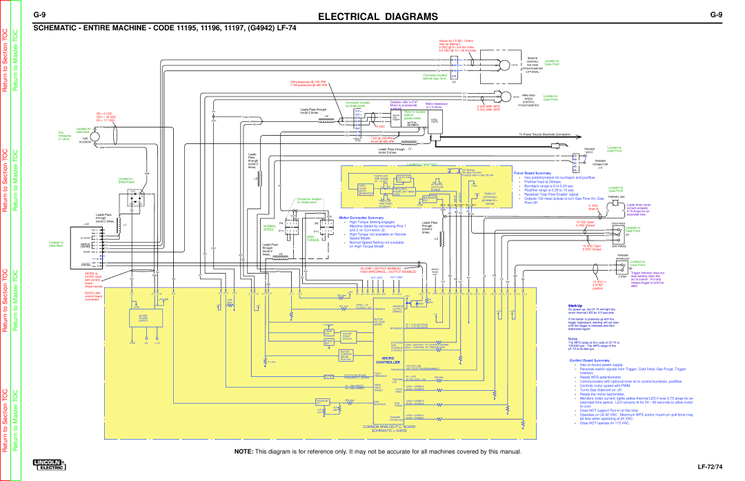
| • Has potentiometers for burnback and postflow. |
|
|
| ||||||||||
|
|
| Located on |
|
|
|
|
|
|
|
| L5 |
|
|
|
|
|
|
|
|
|
|
|
|
|
|
| TIME RANGE |
|
|
|
|
|
|
|
|
|
|
|
|
|
|
|
| |||||||||
|
|
| Sheet Panel |
|
|
|
|
|
|
|
|
|
|
|
|
|
|
|
|
|
|
|
|
|
|
|
| .25 - 10 SEC | POT. |
|
|
|
| A | c |
|
|
|
|
|
|
|
|
| • | Preflow fixed at 30msec. |
|
|
|
|
| ||
|
|
|
|
|
|
|
|
|
|
|
|
|
|
|
|
|
|
|
|
|
|
|
|
|
|
|
|
|
|
|
|
|
|
|
|
|
|
|
|
|
|
|
|
|
| ||||||||
|
|
|
|
|
|
|
|
|
|
|
|
|
|
| 551 |
|
|
|
|
|
|
|
|
|
|
| FIXED |
| c | D |
|
|
|
| 5V SIGNAL |
|
|
| COM |
|
|
|
| • Burnback range is 0 to 0.25 sec. |
|
|
|
| |||||
|
|
|
|
|
|
|
|
|
|
|
|
|
|
|
|
|
|
|
|
|
|
|
|
|
|
|
|
|
|
| GAS FLOW |
|
|
|
|
|
|
|
| Located on |
| ||||||||||||
|
|
|
|
|
|
|
|
|
|
|
|
|
|
|
|
|
|
|
|
|
|
|
|
|
|
| PULSE |
|
| PREFLOW & |
|
| ENABLE |
|
|
|
|
|
|
|
|
| • | Postflow range is 0.25 to 10 sec. |
|
| |||||||
|
|
|
|
|
|
|
|
|
|
|
|
|
|
|
|
|
|
|
|
|
|
|
|
|
|
| WIDTH |
|
|
|
|
|
|
|
|
|
|
|
|
|
| Case Front |
| ||||||||||
|
|
|
|
| + | 552A |
|
|
|
|
|
|
|
|
|
|
|
|
|
|
|
|
|
|
|
|
| POSTFLOW TIMER |
|
|
|
|
|
| OUTPUT |
| +15V | TIMER KIT |
|
|
|
| |||||||||||
|
|
|
|
|
|
|
|
|
|
|
|
|
|
|
|
|
|
|
|
|
|
|
| GENERATOR |
| LOGIC |
|
|
|
|
|
|
| INPUT |
|
|
| • Receives “Gas Flow Enable” signal. |
|
|
|
| |||||||||||
|
|
|
|
|
|
|
|
|
|
|
|
|
|
|
|
|
|
|
|
|
|
|
|
|
|
|
| PREFLOW |
| POT |
|
|
|
|
|
| SCHEMATIC = |
|
|
|
|
|
|
| THERMAL LED |
| |||||||
|
|
|
|
|
|
|
|
|
|
|
|
|
|
|
|
|
|
|
| Connector located |
|
|
|
|
|
|
| A | b |
| BURNBACK |
|
|
|
|
|
| (OPTIONAL) |
|
| • Outputs 100 msec pulses to turn Gas Flow On, Gas |
| |||||||||||
|
|
|
| - |
|
|
|
|
|
|
|
|
|
|
|
|
|
|
| on sheet panel |
|
|
|
|
|
|
| TIME FIXED |
| COM |
|
|
| M20336 |
|
|
| Flow Off. |
|
| 5 VDC |
|
| Lights when motor | |||||||||
|
|
|
|
|
|
|
|
|
|
|
|
|
|
|
|
|
|
|
|
|
|
|
|
|
|
|
|
| AT 30msec |
|
|
|
|
|
|
|
|
|
|
|
|
|
| ||||||||||
|
|
|
|
|
|
|
|
|
|
|
|
|
|
|
|
|
|
|
|
|
|
|
|
|
|
|
|
|
|
|
|
|
|
|
|
|
|
|
|
|
|
|
|
|
|
|
|
|
| current exceeds | |||
|
|
| 41 | 580 | 42 |
|
|
|
|
|
|
|
|
|
|
|
|
|
|
|
|
|
|
|
|
|
|
|
|
|
|
|
|
|
| 606A |
|
|
|
|
|
|
|
|
|
|
|
|
| when lit | 1B |
| |
|
|
|
|
|
|
|
|
|
|
|
|
|
|
|
|
|
|
|
|
|
|
|
|
|
|
|
|
|
|
|
|
|
|
|
| 601 |
|
|
|
|
|
|
|
|
| 1W | 3.75 Amps for an | ||||||
|
|
|
|
|
|
|
|
|
|
|
|
|
|
|
|
|
|
|
|
| 522 |
|
|
|
|
|
|
|
|
|
|
|
|
|
|
| 605 | 608 | 607 |
|
|
|
|
|
|
|
|
|
|
|
| ||
|
| Leads Pass |
|
|
|
|
|
|
|
|
|
|
|
|
| 551A |
|
|
|
|
|
|
|
|
|
|
|
|
|
|
|
|
|
|
|
|
| 515A |
|
|
|
|
|
|
|
|
|
|
| extended time. | |||
|
| through |
|
|
|
|
|
|
|
|
|
|
|
|
|
|
| 521 |
|
| 551B | Motor Connecter Summary |
|
|
|
|
|
|
|
|
|
|
|
| 1B |
|
|
|
|
|
|
|
|
|
|
| |||||||
|
|
|
|
|
|
|
|
|
|
|
|
|
|
|
| 551A |
|
|
|
|
|
|
|
|
|
|
|
|
|
|
|
|
|
|
|
|
|
|
|
|
|
|
|
| |||||||||
| J12 | toroid 2 times. | L1 |
|
|
|
|
|
|
|
|
|
| P4 | 1 | 2 | 3 | 4 |
| P6 | 1 | 2 | 3 | 4 | • High Torque Setting engages |
| Leads Pass |
|
|
|
|
|
|
|
|
|
|
|
|
| 15 VDC Open | COLD FEED |
| ||||||||||
|
|
|
|
|
|
|
|
|
|
|
| NORMAL |
| Machine Select by connecting Pins 1 | through |
|
|
|
|
|
|
|
|
|
|
|
|
| 0 VDC Closed |
| |||||||||||||||||||||||
|
|
|
|
|
|
|
|
|
|
|
|
|
|
|
|
|
|
|
|
|
|
|
|
|
|
|
|
|
|
|
|
|
|
|
|
|
|
| Located on | ||||||||||||||
|
| J |
|
|
|
|
|
|
|
|
|
|
| SPEED |
|
|
|
|
|
|
|
|
|
|
| and 2 on Connector J2. |
|
| toroid 2 |
|
|
|
|
|
|
|
|
|
|
|
|
|
|
| 558 | ||||||||
|
|
|
|
|
|
|
|
|
|
|
|
| P11 | 1 | 2 | 3 | 4 |
| P11 | 1 | 2 | 3 | 4 |
|
|
|
|
|
|
|
|
|
|
|
|
|
|
|
|
| Case Front | ||||||||||||
|
| L |
|
|
|
|
|
|
|
|
|
|
|
|
| • High Torque not available on Normal | times. |
|
|
|
|
|
|
|
|
|
|
|
|
|
|
|
| 515A | |||||||||||||||||||
|
|
|
|
|
|
|
|
|
|
|
|
|
|
|
|
|
|
|
|
|
|
|
|
|
|
|
|
|
|
|
|
|
|
|
|
|
|
|
|
| S1 | ||||||||||||
|
| I | 41 |
|
|
|
|
|
|
|
|
|
|
|
|
|
|
|
|
| HIGH |
|
|
|
|
|
|
|
|
|
|
|
|
|
|
|
|
|
|
|
|
|
|
| 515 | ||||||||
|
|
|
|
|
|
|
|
|
|
|
|
|
| B |
|
|
|
| B |
|
| Speed Model. |
|
|
|
|
|
|
|
|
|
|
|
|
|
|
|
|
|
|
|
|
|
|
|
|
| ||||||
| K | 42 |
|
|
|
|
|
|
|
|
|
|
|
|
|
|
|
|
|
|
|
|
|
|
|
|
| L3 |
|
|
|
|
|
|
|
|
|
|
|
|
|
|
|
|
|
| |||||||
Located on | REMOTE | G | 75A |
|
|
|
|
|
|
|
|
|
|
|
|
|
|
|
|
| TORQUE |
|
|
|
| • Normal Speed Setting not available |
|
|
|
|
|
|
|
|
|
|
|
|
|
|
|
|
|
|
|
| 559 |
|
| ||||
|
|
|
|
|
|
|
|
|
| Leads Pass |
|
|
|
|
|
|
|
|
|
|
|
|
|
|
|
|
|
|
|
|
|
|
|
|
|
|
|
|
|
|
|
|
|
| |||||||||
Case Back | VOLTAGE | F | 76A |
|
|
|
|
|
|
|
|
|
|
|
|
| A |
|
|
|
|
|
|
| on High Torque Model. |
|
|
|
|
|
|
|
|
|
|
|
|
|
|
|
|
|
|
|
| 15 VDC Open | GAS PURGE |
| |||||
CONTROL | E | 77A |
|
|
|
|
|
| 575C |
|
|
| through |
|
|
|
|
|
|
|
| A |
|
|
|
|
|
|
|
|
|
|
|
|
|
|
|
|
|
|
|
|
|
| |||||||||
|
|
|
|
|
|
|
|
|
|
|
|
|
|
|
|
|
|
|
|
|
|
|
|
|
|
|
|
|
|
|
|
|
|
|
|
|
|
|
|
|
|
|
|
| 0 VDC Closed |
|
|
| |||||
| SENSE |
| 67 |
|
|
|
|
|
|
|
|
|
| toroid 2 |
|
|
|
|
|
|
|
|
|
|
|
|
|
|
|
|
|
|
|
|
|
|
|
|
|
|
|
|
|
|
|
|
|
|
|
|
|
| |
| N |
|
|
|
|
|
|
|
|
|
| L6 |
|
|
|
|
|
|
|
|
|
|
|
|
|
|
|
|
|
|
|
|
|
|
|
|
|
|
|
|
|
|
|
|
|
|
|
|
|
| |||
|
|
|
|
|
|
|
|
|
| 576 |
|
| 562 | times. |
|
|
|
|
|
|
|
|
|
|
|
|
|
|
|
|
|
|
|
|
|
|
|
|
|
|
|
|
|
|
|
|
|
|
| TRIGGER | |||
|
| M |
|
|
|
|
|
|
|
|
|
| 563 |
|
|
|
|
|
|
|
|
|
|
|
|
|
|
|
|
|
|
|
|
|
|
|
|
|
|
|
|
|
|
|
|
|
|
|
|
| INTERLOCK | ||
| OUTPUT | C | 2 |
|
|
|
|
|
|
|
|
|
|
|
|
|
|
|
|
|
|
|
|
|
|
|
|
|
|
|
|
|
|
|
|
|
|
|
|
|
|
|
|
|
|
|
|
|
|
|
|
| Located on |
|
|
|
|
|
|
|
|
|
|
|
|
|
|
|
|
|
|
|
|
|
|
|
|
|
|
|
|
|
|
|
|
|
|
|
|
|
|
|
|
|
|
|
|
|
|
|
| 589 |
| Case Front | |||
| CONTROL | D | 4 |
|
|
|
|
|
|
|
|
|
|
|
|
|
|
|
|
|
|
|
|
|
|
|
|
|
|
|
|
|
|
|
|
|
|
|
|
|
|
|
|
|
|
|
|
|
|
|
| ||
|
|
|
|
|
|
|
|
|
|
|
|
|
| 556 |
|
|
|
|
|
|
|
|
|
|
|
| 20 OHM = OUTPUT ENABLED |
|
|
|
| MOLEX |
|
|
|
|
|
|
|
|
|
|
|
|
|
|
| 587 |
| S2 | |||
|
|
|
|
|
|
|
| 552 |
|
|
|
|
| 554 |
|
|
|
|
| 522 |
|
|
|
|
| HIGH IMPEDANCE = OUTPUT DISABLED |
|
| INDEX |
|
|
|
|
|
|
|
|
|
|
|
|
|
|
|
| Trigger Interlock does not | |||||||
| 38VDC at |
|
|
|
|
|
|
|
|
|
|
|
|
|
|
|
|
|
|
|
|
|
|
|
|
|
|
|
|
|
|
|
|
|
|
|
|
|
|
| |||||||||||||
|
|
|
|
| 552A |
| 577 |
|
|
|
|
|
|
|
|
|
|
|
|
|
|
|
|
|
|
|
|
|
|
|
| KEY |
|
|
|
|
|
|
| 558 |
|
|
|
|
|
|
|
|
| ||||
| 42VAC input |
|
|
|
|
|
|
|
|
|
|
|
|
|
|
|
|
|
|
|
|
|
|
|
|
|
| 4 |
|
|
| 605 |
|
|
|
| 1W |
|
| 589 |
|
|
|
| stop welding when the | ||||||||
|
|
|
|
|
|
|
|
|
|
|
|
|
|
|
| 521 |
|
|
|
|
|
| NOT USED | NOT USED |
|
|
|
|
|
|
| 601 |
|
|
|
|
|
|
| ||||||||||||||
|
|
|
|
|
|
|
|
|
|
|
|
|
|
|
|
|
|
|
|
|
|
|
|
|
|
|
|
|
|
|
|
|
|
|
|
|
|
|
|
|
|
|
| ||||||||||
| with control |
| 580 |
|
|
|
| 553 |
|
|
|
| A |
|
|
|
|
|
|
|
|
|
|
|
|
|
|
|
|
|
| 2 |
|
| 606 |
| 608 | 607 |
|
|
|
| 515 | 559 |
| 587 |
|
| 15 VDC in |
| arc is broken. Pull and | ||
| board |
|
|
|
|
|
|
|
|
|
|
|
|
|
|
|
|
|
|
|
|
|
|
|
|
|
|
|
|
|
|
|
|
|
|
|
|
|
|
|
|
|
|
|
| release trigger to end the | |||||||
|
|
|
|
|
|
|
|
|
|
|
|
| 550 |
|
|
|
|
|
|
|
|
|
|
|
|
|
|
|
|
|
|
|
|
|
|
|
|
|
|
|
|
|
|
|
|
|
| ||||||
| disconnected. |
|
|
|
|
|
|
|
|
|
|
|
|
|
|
|
|
|
|
|
|
|
|
|
|
|
|
|
|
|
|
|
|
|
|
|
|
|
|
|
|
|
|
|
|
|
| 2 STEP |
|
| weld. | ||
|
|
|
|
|
|
|
|
|
|
|
|
|
|
|
|
|
|
|
|
|
|
|
|
|
|
|
|
|
|
|
|
|
|
|
|
|
|
|
|
|
|
|
|
|
|
|
|
|
| ||||
|
|
|
|
|
|
|
|
|
|
|
|
|
|
|
|
|
|
|
|
|
|
|
|
|
|
|
|
|
|
|
|
|
|
|
|
|
|
|
|
|
|
|
|
|
|
|
|
|
| position |
|
|
|
| 60VDC with |
|
|
|
|
|
|
|
|
|
|
| +15V |
|
|
|
|
|
|
| |||||||||||||||||||||||||||||||||
| control board |
|
|
|
|
|
|
|
|
|
|
|
|
|
|
|
|
|
|
|
|
|
|
| 750 ohm |
|
|
|
| +15V |
|
|
|
|
|
|
|
|
|
|
|
|
|
|
|
|
|
|
|
|
| ||
| connected |
|
|
|
|
| +POWER |
|
| 100K |
|
|
|
|
|
|
|
|
|
|
|
|
|
|
|
|
|
|
|
|
| 20 |
|
|
|
|
|
|
|
|
|
|
|
|
|
|
|
|
|
| |||
|
|
|
|
|
|
|
|
|
|
| ohm |
|
|
|
|
|
|
|
|
|
|
|
|
|
|
|
|
|
|
|
| MOV |
| ohm |
|
|
|
|
|
|
|
|
|
|
|
|
|
|
|
|
| ||
|
|
|
| COM |
|
|
|
| +5V |
|
| +5V |
|
|
|
|
|
|
|
|
|
|
|
| 750 ohm | OPEN = 0V |
|
| MACHINE |
|
|
|
|
|
|
|
|
|
|
|
|
|
|
|
|
|
|
|
| ||||
|
|
|
|
|
|
|
|
|
|
|
|
|
|
|
|
|
|
|
|
|
|
|
|
|
|
|
|
|
|
|
|
|
|
|
|
|
|
|
|
|
|
|
|
| |||||||||
|
|
|
|
|
|
|
|
|
|
|
|
|
|
|
|
|
|
|
|
|
|
|
|
|
|
| CLOSED = 8V | TRIGGER | OUTPUT |
|
|
|
|
|
|
|
|
|
|
|
|
|
|
|
|
|
| On |
|
| |||
|
|
|
|
|
|
|
|
|
|
|
|
|
|
|
|
|
|
|
|
|
|
|
|
|
|
|
|
|
|
|
|
|
|
|
|
|
|
|
|
| +15V | +15V |
|
|
|
| |||||||
|
|
|
|
|
|
|
|
|
|
|
|
|
|
|
|
|
|
|
|
|
|
|
|
|
|
|
|
|
| ENABLE |
|
|
|
|
|
|
|
|
|
|
|
|
|
| motor thermal LED for 0.5 seconds. |
|
| ||||||
|
|
|
|
|
|
|
|
|
|
|
|
|
|
|
|
|
|
|
|
|
|
|
|
|
|
|
|
|
|
|
|
|
|
| +5V |
|
|
|
|
|
|
|
|
|
|
|
|
|
|
| |||
|
|
|
|
| BOARD |
|
|
|
|
|
|
|
|
|
|
|
|
|
|
|
|
|
|
|
|
|
|
|
|
|
|
|
|
|
|
|
|
|
|
|
|
|
|
|
|
|
|
|
|
|
| ||
|
|
|
|
|
|
|
|
|
|
|
|
|
|
|
|
|
|
|
|
|
|
|
|
|
|
|
|
|
|
|
|
|
|
|
|
|
|
|
|
|
|
|
|
|
|
|
|
|
|
|
| ||
|
|
|
|
| POWER |
|
|
|
|
|
|
|
|
|
|
|
|
|
|
|
|
|
|
|
|
|
| MOTOR |
|
|
|
|
|
|
|
|
|
|
|
|
|
|
|
|
|
|
| If the feeder is |
|
| |||
|
|
|
|
| SUPPLY |
|
|
|
|
|
|
|
|
|
|
|
|
|
|
|
|
|
|
|
|
|
| VOLTAGE |
|
|
|
|
|
|
|
|
|
|
|
|
|
|
|
|
|
|
| trigger depressed, welding will not start |
|
| |||
|
|
|
|
|
|
|
|
|
|
|
|
|
|
|
|
|
|
|
|
|
| + POWER |
|
| SENSE |
| 0V = 0.02 SECONDS |
|
|
|
|
|
|
|
|
|
|
|
|
|
|
| until the trigger is released and then |
|
| ||||||||
|
|
|
|
|
|
|
|
|
|
|
|
|
|
|
|
|
|
|
|
|
|
| DRIVE |
|
|
|
| BURNBACK | 5V = 0.25 SECONDS |
|
|
|
|
|
|
|
|
|
|
|
|
|
|
| depressed again. |
|
|
| |||||
|
|
|
|
|
|
|
|
|
|
|
|
|
|
|
|
|
|
|
|
|
|
| MOTOR |
|
|
|
|
|
|
|
|
|
|
|
|
|
|
|
|
|
|
|
|
|
|
|
|
|
|
| |||
|
|
|
|
|
|
|
|
|
|
|
|
|
|
|
|
|
|
|
|
|
|
| FET |
|
|
|
|
|
|
|
|
|
|
|
|
|
|
|
|
|
|
|
|
|
|
|
|
|
|
|
| ||
|
|
|
|
|
|
|
|
|
|
|
|
|
|
|
|
|
|
|
|
|
|
|
|
|
| DRIVE |
|
|
|
|
|
|
|
|
|
|
|
|
|
|
|
|
|
|
|
|
|
| Notes |
|
|
|
|
|
|
|
|
|
|
|
|
|
|
|
|
|
|
|
|
|
|
|
|
|
|
| BRAKE | CIRCUIT |
|
|
|
|
|
|
|
|
|
|
|
|
|
|
|
|
|
|
|
|
|
|
|
|
|
| |||
|
|
|
| COM |
| +5V | +15V |
|
|
|
|
|
|
|
|
|
|
|
|
|
|
|
|
|
| EXTERNAL |
|
|
|
|
|
|
|
|
|
|
|
|
|
|
|
|
|
| The WFS range of this code of |
|
| ||||||
|
|
|
|
|
|
|
|
|
|
|
|
|
|
|
|
|
|
| FET |
|
|
|
|
| LOW = CONTROL AT CONTROL BOARD |
|
|
|
|
|
|
|
|
|
|
|
|
| |||||||||||||||
|
|
|
|
|
|
|
|
|
|
|
|
|
|
|
|
|
|
|
|
|
|
|
| GAS |
|
|
|
|
|
|
|
|
|
|
|
|
| ||||||||||||||||
|
|
|
|
|
|
|
|
|
|
|
|
|
|
|
|
|
|
|
|
|
|
|
|
|
|
|
|
|
|
|
|
|
|
|
|
|
|
|
|
|
|
| |||||||||||
|
|
|
|
|
|
|
|
|
|
|
|
|
|
|
|
|
|
|
|
|
|
|
|
|
|
|
|
|
| SOLENOID | HIGH = CONTROL AT TIMER BOARD |
|
|
|
|
|
|
|
|
|
|
|
|
|
|
| |||||||
|
|
|
|
|
|
|
|
|
|
|
|
|
|
|
|
|
|
|
|
|
|
|
|
|
| MOTOR |
|
|
| CONTROL |
|
|
|
|
|
|
|
|
|
|
|
|
|
|
|
|
|
|
|
|
| ||
|
|
|
|
|
|
|
|
|
|
|
|
|
|
|
|
|
|
|
|
|
|
|
|
|
|
|
|
|
|
|
|
|
|
|
|
|
|
|
|
|
|
|
|
|
|
|
|
|
|
|
| ||
|
|
|
|
|
|
|
|
|
|
|
|
|
|
|
|
|
|
|
|
|
|
|
|
|
|
|
|
|
|
|
|
|
|
|
|
|
|
|
|
|
|
|
|
|
|
|
|
|
|
|
|
| |
|
|
|
|
|
|
|
|
|
|
|
|
|
|
|
|
|
|
|
|
|
|
|
|
|
| CURRENT |
|
|
|
|
|
|
|
|
|
|
|
|
|
|
|
|
|
|
|
|
|
|
|
|
|
|
|
|
|
|
|
|
|
|
|
|
|
|
|
|
|
|
|
|
|
|
|
|
|
|
|
|
| SENSE |
|
| MICRO |
|
|
|
|
|
|
|
|
|
|
|
|
|
|
|
|
|
|
|
|
|
|
| |
|
|
|
|
|
|
|
|
|
|
|
|
|
|
|
|
|
|
|
|
|
|
|
|
|
| SCALING |
|
|
|
|
|
|
|
|
|
|
|
|
|
|
|
|
|
|
|
| Control Board Summary |
|
| ||||
|
|
|
|
|
|
|
|
|
|
|
|
|
| 0.1 ohm |
|
|
|
|
|
|
|
|
|
|
|
|
|
| CONTROLLER |
|
|
|
|
|
|
|
|
|
|
|
|
|
|
|
|
|
|
|
| ||||
|
|
|
|
|
|
|
|
|
|
|
|
|
|
|
|
|
|
|
|
|
|
|
|
|
|
|
|
|
|
|
|
|
|
|
|
|
|
|
|
|
|
|
|
|
| • Has |
| ||||||
|
|
|
|
|
|
|
|
|
|
|
|
|
|
|
|
|
|
|
|
|
|
|
|
|
|
|
|
|
|
|
| DO NOT USE |
|
|
|
|
|
|
|
|
|
|
|
|
|
|
|
|
| ||||
|
|
|
|
|
|
|
|
|
|
|
|
|
|
|
|
|
|
|
|
|
|
|
|
|
|
|
|
|
| PROGRAM |
| NOT FIELD PROGRAMMABLE |
|
|
|
|
|
|
|
|
|
|
|
| • Receives switch signals from Trigger, Cold Feed, Gas Purge, Trigger | ||||||||
|
|
|
|
|
|
|
|
|
|
|
|
|
|
|
|
|
|
|
|
|
|
|
|
|
|
| TACH |
|
|
|
|
|
|
|
|
|
|
|
|
|
|
|
|
|
|
|
| Interlock |
|
|
| ||
|
|
|
|
|
|
|
|
|
|
|
|
|
|
|
|
|
|
|
|
|
|
| FILTER |
| FEEDBACK |
| 5V = OFF |
|
| 200 ohm |
|
|
|
|
|
|
|
|
|
|
|
| • | Reads WFS potentiometer. |
| ||||||||
|
|
|
|
|
|
|
|
|
|
|
|
|
|
|
|
|
|
|
|
|
|
| FREQUENCY = SPEED |
|
|
|
|
|
|
|
|
|
|
|
|
|
|
|
|
| |||||||||||||
|
|
|
|
|
|
|
|
|
|
|
|
|
|
|
|
|
|
|
|
|
|
|
|
| THERMAL |
|
|
|
|
|
|
|
|
|
|
|
|
|
|
| |||||||||||||
|
|
|
|
|
|
|
|
|
|
|
|
|
|
|
|
|
|
|
|
|
|
|
|
|
|
|
|
|
| 4V OR LESS = ON |
|
|
|
|
|
|
|
|
|
|
|
|
|
|
|
| • Communicates with optional timer kit to control burnback, postflow. | ||||||
|
|
|
|
|
|
|
|
|
|
|
|
|
|
|
|
|
|
|
|
|
|
|
|
|
| 0V = MIN SPEED |
|
| LED |
| LOW = DISABLE |
|
|
|
|
|
|
|
|
|
|
|
|
|
|
|
| ||||||
|
|
|
|
|
|
|
|
|
|
|
|
|
|
|
|
|
|
|
|
|
|
|
|
|
|
| WIRE |
|
|
|
|
|
|
|
|
|
|
|
|
|
|
|
|
|
| • Controls motor speed with PWM. | |||||||
|
|
|
|
|
|
|
|
|
|
|
|
|
|
|
|
|
|
|
|
|
|
|
|
|
| 5V = MAX SPEED |
| FEED | COLD |
| HIGH = ENABLE |
|
|
|
|
|
|
|
|
|
|
|
|
|
|
|
| • Turns Gas Solenoid on, off. |
| ||||
|
|
|
|
|
|
|
|
|
|
|
|
|
|
|
|
|
|
|
|
|
|
|
|
|
|
| SPEED |
|
|
|
|
|
|
|
|
|
|
|
|
|
|
|
|
|
| ||||||||
|
|
|
|
|
|
|
|
|
|
|
|
|
|
|
|
|
|
|
|
|
|
|
|
|
|
|
|
|
|
|
|
|
|
|
|
|
|
|
|
|
|
|
|
|
|
| |||||||
|
|
|
|
|
|
|
|
|
|
|
|
|
|
|
|
|
|
|
|
|
|
|
|
|
|
|
|
|
| FEED |
|
|
|
|
|
|
|
|
|
|
|
|
|
|
|
|
|
| • Reads the motor tachometer. |
| |||
|
|
|
|
|
|
|
|
|
|
|
|
|
|
|
|
|
|
|
|
|
|
|
|
|
|
|
|
|
|
|
|
|
|
|
|
|
|
|
|
|
|
|
|
|
|
|
|
|
| ||||
|
|
|
|
|
|
|
|
|
|
|
|
|
|
|
|
|
|
|
|
| SOLENOID |
| 200 ohm |
|
|
|
|
| LOW = DISABLE |
|
|
|
|
|
|
|
|
|
|
|
|
|
|
|
| • Monitors motor current, lights yellow thermal LED if over 3.75 amps for an | |||||||
|
|
|
|
|
|
|
|
|
|
|
|
|
|
|
|
|
|
|
|
|
|
|
| GAS |
|
|
|
|
|
|
|
|
|
|
|
|
|
|
|
|
|
|
| extended time period. LED remains lit for 30 – 60 seconds to allow motor | |||||||||
|
|
|
|
|
|
|
|
|
|
|
|
|
|
|
|
|
|
|
|
| FET |
|
|
|
|
|
|
| GAS |
| HIGH = ENABLE |
|
|
|
|
|
|
|
|
|
|
|
|
|
|
|
|
| |||||
|
|
|
|
|
|
|
|
|
|
|
|
|
|
|
|
|
|
|
|
|
|
|
|
|
| 0.25 |
|
| SOLENOID | PURGE |
|
|
|
|
|
|
|
|
|
|
|
|
|
|
|
|
|
|
| to cool. |
|
|
|
|
|
|
|
|
|
|
|
|
|
|
|
|
|
|
|
|
|
|
|
|
|
|
|
|
|
|
|
|
|
|
|
|
|
|
|
|
|
|
|
|
|
|
|
|
|
|
|
|
|
|
|
| |
|
|
|
|
|
|
|
|
|
|
|
|
|
|
|
|
|
|
|
|
| 10K |
|
|
|
| ohm |
|
|
|
|
|
|
|
|
|
|
|
|
|
|
|
|
|
|
|
|
|
| • Does NOT support | ||||
|
|
|
|
|
|
|
|
|
|
|
|
|
|
|
|
|
|
|
|
| ohm |
|
|
|
|
|
|
|
|
|
|
|
|
|
|
|
|
|
|
|
|
|
|
|
|
|
|
| • | Operates on | |||
|
|
|
|
|
|
|
|
|
|
|
|
|
|
|
|
|
|
|
|
|
|
|
|
|
|
|
|
|
| TRIGGER |
| LOW = DISABLE |
|
|
|
|
|
|
|
|
|
|
|
|
|
|
|
| |||||
|
|
|
|
|
|
|
|
|
|
|
|
|
|
|
|
|
|
|
|
|
|
|
|
|
|
|
|
|
|
| HIGH = ENABLE |
|
|
|
|
|
|
|
|
|
|
|
|
|
|
|
|
| be less when operating at 24 VAC. | ||||
|
|
|
|
|
|
|
|
|
|
|
|
|
|
|
|
|
|
|
|
|
|
|
|
|
|
|
|
|
| INTERLOCK |
|
|
|
|
|
|
|
|
|
|
|
|
|
|
|
|
|
| • Does NOT operate on 115 VAC. | ||||
|
|
|
|
|
|
|
|
|
|
|
|
|
|
|
|
|
|
|
|
|
|
|
|
|
|
|
|
|
|
|
|
|
|
|
|
|
|
|
|
|
|
|
|
|
|
|
|
| |||||
COMMON ANALOG P.C. BOARD
SCHEMATIC = G4559
NOTE: This diagram is for reference only. It may not be accurate for all machines covered by this manual.