Section TOC
Master TOC
THEORY OF OPERATION
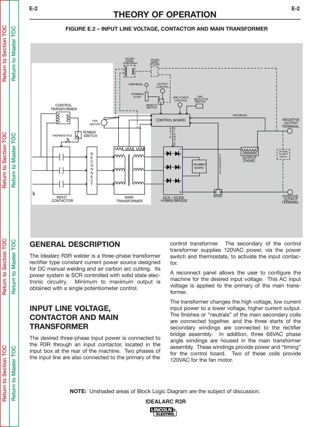
FIGURE E.2 – INPUT LINE VOLTAGE, CONTACTOR AND MAIN TRANSFORMER
CONTROL
TRANSFORMER
FAN
MOTOR
| OPTIONAL |
|
|
|
|
|
| OPTIONAL | |||||||||||
|
|
|
|
|
|
| |||||||||||||
| AMPTROL |
|
|
|
|
|
|
| |||||||||||
TRANSFORMER |
|
|
|
|
|
| AMPTROL | ||||||||||||
|
|
|
|
|
|
|
|
|
|
|
|
|
|
| PC BOARD | ||||
|
|
|
|
|
|
|
|
|
|
|
|
|
|
|
|
|
|
|
|
|
|
|
|
|
|
|
|
|
|
|
|
|
|
|
|
|
|
|
|
|
|
|
|
|
|
|
|
|
|
|
|
|
|
|
|
|
|
|
|
AMPHENOL | OUTPUT |
|
| CONTROL |
|
TERMINAL |
| DIAL |
STRIP | ARC FORCE | |
| CONTROL | SELECTOR |
| SWITCH | |
|
| |
| REMOTE |
|
| SWITCH |
|
FEEDBACK
CONTROL BOARD
NEGATIVE OUTPUT TERMINAL
Return to Section TOC
Return to Master TOC
POWER
THERMOSTATS ![]() SWITCH
SWITCH
R
E
C
O
N
N
E
C
T
INPUT
CONTACTOR
MAIN |
TRANSFORMER |
G | S |
A | I |
T | G |
E | N |
| A |
| L |
| S |
| SNUBBER |
| BOARD |
SCR / DIODE
HYBRID BRIDGE
F
EOUTPUT
E | CHOKE |
D |
|
B |
|
A |
|
C |
|
K |
|
SHUNT
OPTIONAL
POLARITY
SWITCH
POSITIVE OUTPUT TERMINAL
Return to Section TOC
to Section TOC
Return to Master TOC
to Master TOC
GENERAL DESCRIPTION
The Idealarc R3R welder is a
INPUT LINE VOLTAGE,
CONTACTOR AND MAIN
TRANSFORMER
The desired
control transformer. The secondary of the control transformer supplies 120VAC power, via the power switch and thermostats, to activate the input contac- tor.
A reconnect panel allows the user to configure the machine for the desired input voltage. This AC input voltage is applied to the primary of the main trans- former.
The transformer changes the high voltage, low current input power to a lower voltage, higher current output. The finishes or “neutrals” of the main secondary coils are connected together, and the three starts of the secondary windings are connected to the rectifier bridge assembly. In addition, three 66VAC phase angle windings are housed in the main transformer assembly. These windings provide power and “timing” for the control board. Two of these coils provide 120VAC for the fan motor.
Return
Return
NOTE: Unshaded areas of Block Logic Diagram are the subject of discussion.