to Section TOC
to Master TOC
THEORY OF OPERATION
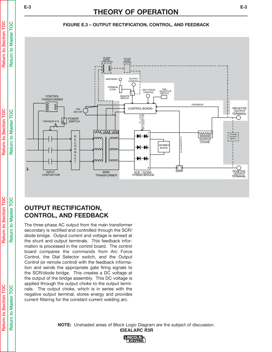
FIGURE E.3 – OUTPUT RECTIFICATION, CONTROL, AND FEEDBACK
Return
TOC
Return
TOC
CONTROL
TRANSFORMER
FAN
MOTOR
| OPTIONAL |
|
|
|
|
|
| OPTIONAL | |||||||||||
|
|
|
|
|
|
| |||||||||||||
| AMPTROL |
|
|
|
|
|
|
| |||||||||||
TRANSFORMER |
|
|
|
|
|
| AMPTROL | ||||||||||||
|
|
|
|
|
|
|
|
|
|
|
|
|
|
| PC BOARD | ||||
|
|
|
|
|
|
|
|
|
|
|
|
|
|
|
|
|
|
|
|
|
|
|
|
|
|
|
|
|
|
|
|
|
|
|
|
|
|
|
|
|
|
|
|
|
|
|
|
|
|
|
|
|
|
|
|
|
|
|
|
AMPHENOL | OUTPUT |
|
| CONTROL |
|
TERMINAL |
| DIAL |
STRIP | ARC FORCE | |
| CONTROL | SELECTOR |
| SWITCH | |
|
| |
| REMOTE |
|
| SWITCH |
|
FEEDBACK
CONTROL BOARD
NEGATIVE OUTPUT TERMINAL
POWER
THERMOSTATS ![]() SWITCH
SWITCH
R
E
C
O
N
N
E
C
T
INPUT
CONTACTOR
MAIN |
TRANSFORMER |
G | S |
A | I |
T | G |
E | N |
| A |
| L |
| S |
| SNUBBER |
| BOARD |
SCR / DIODE
HYBRID BRIDGE
F
EOUTPUT
E | CHOKE |
D |
|
B |
|
A |
|
C |
|
K |
|
SHUNT
OPTIONAL
POLARITY
SWITCH
POSITIVE OUTPUT TERMINAL
Return to Section TOC
Return to Section TOC
Return to Master TOC
Return to Master TOC
OUTPUT RECTIFICATION,
CONTROL, AND FEEDBACK
The
NOTE: Unshaded areas of Block Logic Diagram are the subject of discussion.