TOC
TOC
TROUBLESHOOTING & REPAIR
STATOR/ROTOR REMOVAL AND REPLACEMENT (continued)
Return to Master
Return to Master TOC
Master TOC
6.Install the bottom two end bracket thru- bolts.
Note: The flat washer goes on the top right hand
7.Tap the end bracket with the mallet as necessary to position it. Tighten the bolts to 22 - 25 ft lbs. Alternate tightening in order to pull the assembly together even- ly. As you tighten, look through the brush housing access door and watch the bear- ing to judge end bracket movement and alignment.
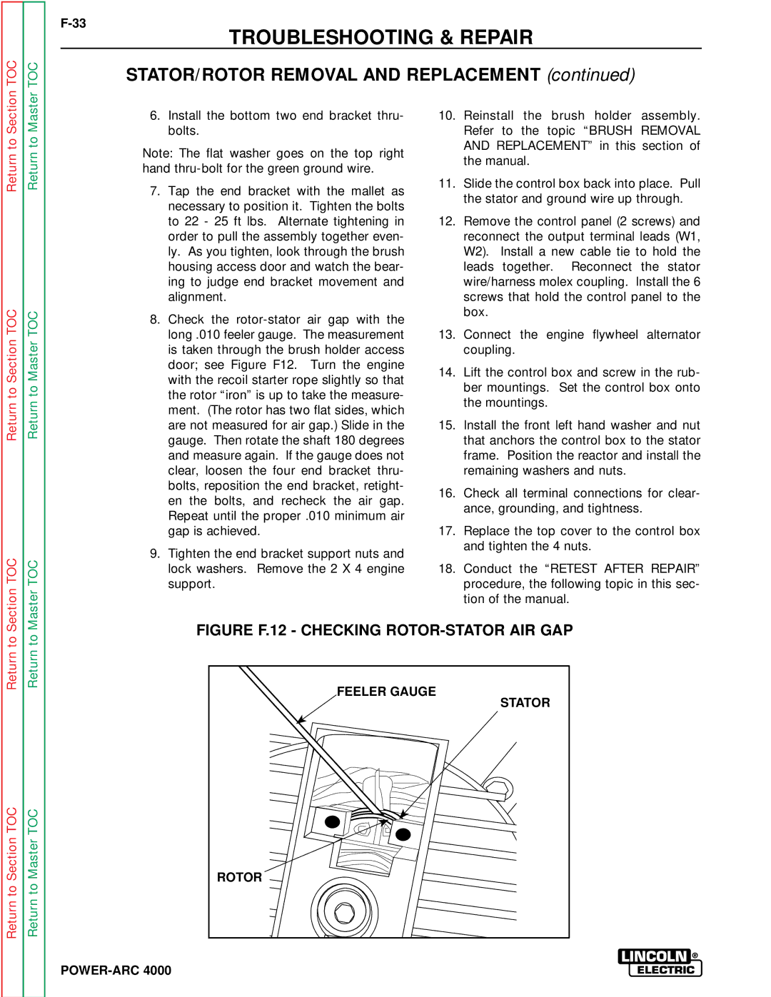
8.Check the
9.Tighten the end bracket support nuts and lock washers. Remove the 2 X 4 engine support.
10.Reinstall the brush holder assembly. Refer to the topic “BRUSH REMOVAL AND REPLACEMENT” in this section of the manual.
11.Slide the control box back into place. Pull the stator and ground wire up through.
12.Remove the control panel (2 screws) and reconnect the output terminal leads (W1, W2). Install a new cable tie to hold the leads together. Reconnect the stator wire/harness molex coupling. Install the 6 screws that hold the control panel to the box.
13.Connect the engine flywheel alternator coupling.
14.Lift the control box and screw in the rub- ber mountings. Set the control box onto the mountings.
15.Install the front left hand washer and nut that anchors the control box to the stator frame. Position the reactor and install the remaining washers and nuts.
16.Check all terminal connections for clear- ance, grounding, and tightness.
17.Replace the top cover to the control box and tighten the 4 nuts.
18.Conduct the “RETEST AFTER REPAIR” procedure, the following topic in this sec- tion of the manual.
Return to
Return to Section TOC
Return to
Return to Master TOC
FIGURE F.12 - CHECKING ROTOR-STATOR AIR GAP
FEELER GAUGE |
STATOR |
ROTOR |