|
| INSTALLATION | ||||
Return to Section TOC | Return to Master TOC |
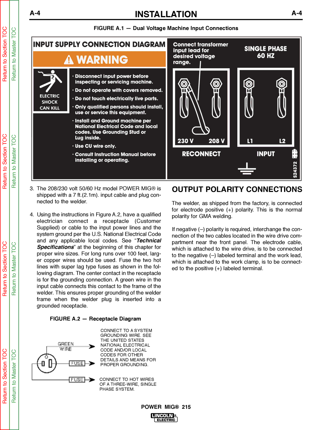
| FIGURE A.1 — Dual Voltage Machine Input Connections |
| ||
|
|
|
| |||
Return to Section TOC | Return to Master TOC | 3. The 208/230 volt 50/60 Hz model POWER MIG® is | OUTPUT POLARITY CONNECTIONS | |||
|
| |||||
|
| shipped with a 7 ft.(2.1m). input cable and plug con- |
|
| ||
|
| nected to the welder. |
| The welder, as shipped from the factory, is connected | ||
|
|
|
| |||
|
| 4. Using the instructions in Figure A.2, have a qualified | for electrode positive (+) polarity. This is the normal | |||
|
| polarity for GMA welding. |
| |||
|
| electrician connect a receptacle (Customer |
| |||
|
|
|
| |||
|
| Supplied) or cable to the input power lines and the | If negative | |||
|
| system ground per the U.S. National Electrical Code | ||||
|
| nection of the two cables located in the wire drive com- | ||||
|
| and any applicable | local codes. See “Technical | |||
TOC | TOC | partment near the front panel. The electrode cable, | ||||
Specifications” at the beginning of this chapter for | ||||||
which is attached to the wire drive, is to be connected | ||||||
proper wire sizes. For long runs over 100 feet, larg- | ||||||
|
| |||||
Section | Master | to the negative | ||||
er copper wires should be used. Fuse the two hot | ||||||
which is attached to the work clamp, is to be connect- | ||||||
lines with super lag type fuses as shown in the fol- | ||||||
ed to the positive (+) labeled terminal. |
| |||||
lowing diagram. The center contact in the receptacle |
| |||||
|
| |||||
to | to |
|
| |||
is for the grounding connection. A green wire in the |
|
| ||||
Return | Return |
|
| |||
input cable connects this contact to the frame of the |
|
| ||||
welder. This ensures proper grounding of the welder |
|
| ||||
|
| frame when the welder plug is inserted into a |
|
| ||
|
| grounded receptacle. |
|
|
| |
FIGURE A.2 — Receptacle Diagram
|
| CONNECT TO A SYSTEM | |
|
| GROUNDING WIRE. SEE | |
|
| THE UNITED STATES | |
TOC |
| NATIONAL ELECTRICAL | |
TOC | CODE AND/OR LOCAL | ||
CODES FOR OTHER | |||
|
| ||
Section | Master | DETAILS AND MEANS FOR | |
PROPER GROUNDING. | |||
|
| ||
to | to | CONNECT TO HOT WIRES | |
OF A | |||
Return | Return | PHASE SYSTEM. | |
|
|
POWER MIG® 215
