Return to Section TOC
Return to Master TOC
THEORY OF OPERATION |
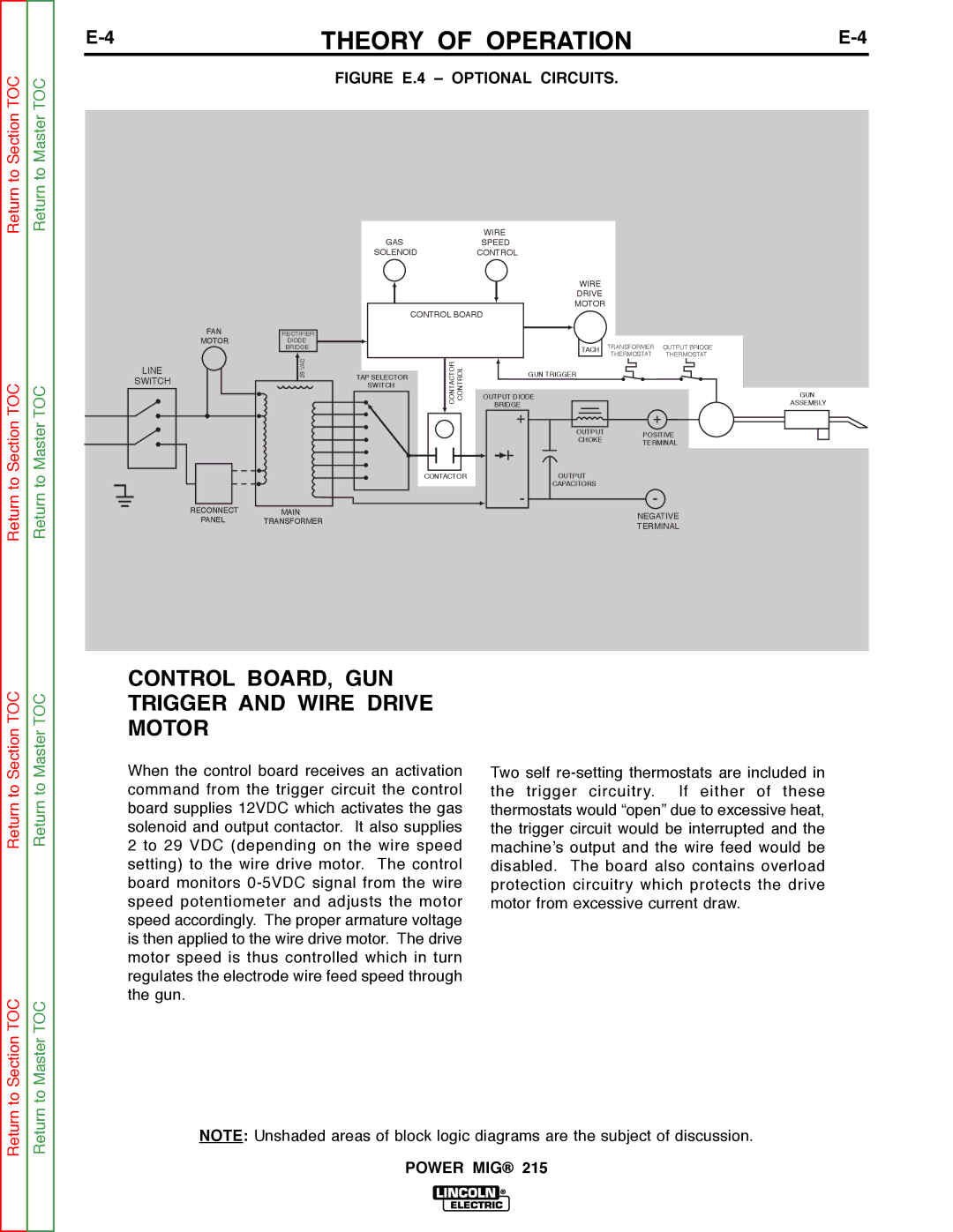
FIGURE E.4 – OPTIONAL CIRCUITS.
WIRE
GASSPEED
SOLENOIDCONTROL
FAN
MOTOR
LINE
SWITCH
RECTIFIER
DIODE
BRIDGE
VAC28TAP SELECTOR SWITCH
CONTROL BOARD
CONTACTOR | CONTROL |
CONTACTOR
WIRE
DRIVE
MOTOR
TACH
GUN TRIGGER
OUTPUT DIODE
BRIDGE
+
OUTPUT
CHOKE
OUTPUT
CAPACITORS
-
TRANSFORMER | OUTPUT BRIDGE | ||||||
THERMOSTAT | THERMOSTAT | ||||||
|
|
|
|
|
|
|
|
|
|
|
|
|
|
|
|
|
|
|
|
|
|
|
|
+
POSITIVE
TERMINAL
-
GUN
ASSEMBLY
Return
Return
RECONNECT
PANEL
MAIN | NEGATIVE | |
TRANSFORMER | ||
TERMINAL | ||
|
Section TOC
Master TOC
CONTROL BOARD, GUN TRIGGER AND WIRE DRIVE MOTOR
Return to
Return to
When the control board receives an activation command from the trigger circuit the control board supplies 12VDC which activates the gas solenoid and output contactor. It also supplies 2 to 29 VDC (depending on the wire speed setting) to the wire drive motor. The control board monitors
Two self
Return to Section TOC
Return to Master TOC
NOTE: Unshaded areas of block logic diagrams are the subject of discussion.