Return to Section TOC
Return to Section TOC
Return to Section TOC
Return to Section TOC
Return to Master TOC
Return to Master TOC
Return to Master TOC
Return to Master TOC
| THEORY OF OPERATION |
| |||||||||||||||
CONTROLS AND OPERATIONAL |
| If the Yellow LED illuminates, and the Red and Green | |||||||||||||||
FEATURES |
|
|
| LEDʼs blink on and off alternately, the unit is unable to | |||||||||||||
| Potentiometer used to | cool itself adequately. Check to make sure the fan is | |||||||||||||||
1. Output Current Knob: A | not obstructed and the fan is operating properly. Prior | ||||||||||||||||
set the output current used during welding, from 5A | to resuming normal operation, the unit must be turned | ||||||||||||||||
to 155A. |
|
|
| off and turned back on to reset this error condition. | |||||||||||||
2. Welding Mode Switch: With three positions, con- |
|
|
|
| WARNING |
| |||||||||||
trols the welding mode of the machine: two for Stick |
|
|
|
|
|
| |||||||||||
welding (Soft and Crisp) and one for Lift TIG weld- | If blinking, the Thermal LED indicates that the input | ||||||||||||||||
ing. |
|
|
| ||||||||||||||
• Soft Stick: |
|
|
|
|
|
|
| For a welding with a low spatter | voltage is out of ranges. |
| |||||||
|
|
|
|
|
|
|
| ||||||||||
|
|
|
|
|
|
|
| ||||||||||
• Crisp Stick: | presence. |
|
| 4. Power On/Off & OUTPUT LEDs: These LEDs (one | |||||||||||||
For an aggressive welding arc, | green and one red) operates as described in the | ||||||||||||||||
|
|
|
|
|
|
|
|
| with an increased Arc stability. |
| table below: |
|
|
| |||
|
|
|
|
|
|
|
|
|
|
|
|
| |||||
• Lift TIG: |
|
|
| When the mode switch is in the Lift |
|
|
|
|
|
| |||||||
|
|
|
|
|
| LED status |
|
| FUNCTION | ||||||||
TIG position, the stick welding functions are disabled |
|
| |||||||||||||||
and the machine is ready for Lift TIG welding. Lift | Green | Red |
| V |
|
| |||||||||||
TIG is a method of starting a TIG weld by first press- | ON | OFF |
|
|
| ||||||||||||
| The machine is turned ON. | ||||||||||||||||
ing the TIG torch electrode on the work piece in |
|
|
|
| ON condition: The machine is at | ||||||||||||
order to create a low current short circuit. Then, the |
|
|
|
| |||||||||||||
electrode is lifted from the work piece to start the TIG |
|
|
| idle | |||||||||||||
arc. | This indicator will turn on when |
|
|
| is present. |
| |||||||||||
3. Thermal LED: | OFF | ON |
| AThe machine is turned ON. | |||||||||||||
the machine is overheated and the output has been |
| ||||||||||||||||
disabled. This normally occurs when the duty cycle |
|
|
|
| On condition: Presence of weld- | ||||||||||||
of the machine has been | exceeded. Leave | the |
|
|
| ing current at the output leads. | |||||||||||
machine on to allow the internal components to cool. |
|
|
| This permanent | LED condition, | ||||||||||||
When the indicator turns off, normal operation is |
|
|
| ||||||||||||||
again possible. |
|
|
|
|
|
| showed at idle | ||||||||||
|
|
|
|
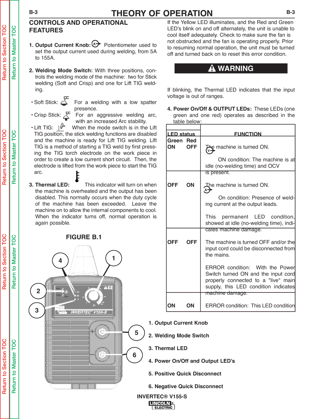
| FIGURE B.1 |
|
| OFF | OFF |
| cates machine damage. | ||||||
|
|
|
|
|
|
|
| The machine is turned OFF and/or the | |||||||||
|
|
|
|
|
|
|
|
|
|
|
|
|
|
| input cord could be disconnected from | ||
4 |
|
|
|
|
|
|
| 1 |
|
|
|
| the mains. | With the Power | |||
|
|
|
|
|
|
|
|
|
|
| ERROR condition: | ||||||
|
|
|
|
|
|
|
|
|
|
|
|
|
|
| Switch turned ON and the input cord | ||
|
|
|
|
|
|
|
|
|
|
|
|
|
|
| properly connected to a "live" main | ||
2 |
|
|
|
|
|
|
|
|
|
|
|
|
|
| supply, this LED condition indicates | ||
|
|
|
|
|
|
|
|
|
|
| ON | ON |
| machine damage. |
| ||
3 |
|
|
|
|
|
|
|
|
|
|
|
| ERROR condition: This LED condition | ||||
|
|
|
|
|
|
|
|
|
| 5 | 1. Output Current Knob |
|
| ||||
|
|
|
|
|
|
|
|
|
| 2. Welding Mode Switch |
|
| |||||
|
|
|
|
|
|
|
|
|
| 6 | 3. Thermal LED |
|
|
| |||
|
|
|
|
|
|
|
|
|
| 4. Power On/Off and Output LEDʼs |
| ||||||
|
|
|
|
|
|
|
|
|
|
| 5. Positive Quick Disconnect |
| |||||
6. Negative Quick Disconnect INVERTEC®
