to Section TOC
to Master TOC
F-20 TROUBLESHOOTING & REPAIRF-20
INPUT BOARD VOLTAGE TEST (CONTINUED)
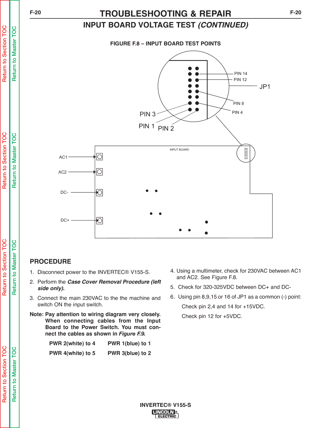
FIGURE F.8 – INPUT BOARD TEST POINTS
Return
Return to Section TOC
Return
Return to Master TOC
PIN 3 ![]()
PIN 1 PIN 2
INPUT BOARD
AC1
AC2
PIN 14
PIN 12
JP1
PIN 8
PIN 4
DC-
DC+
Return to Section TOC
to Section TOC
Return to Master TOC
to Master TOC
PROCEDURE
1. Disconnect power to the INVERTEC® V155-S.
2. Perform the Case Cover Removal Procedure (left
side only).
3. Connect the main 230VAC to the the machine and switch ON the input switch.
Note: Pay attention to wiring diagram very closely. When connecting cables from the Input Board to the Power Switch. You must con- nect the cables as shown in Figure F.9.
PWR 2(white) to 4 | PWR 1(blue) to 1 |
PWR 4(white) to 5 | PWR 3(blue) to 2 |
4.Using a multimeter, check for 230VAC between AC1 and AC2. See Figure F.8.
5.Check for
6.Using pin 8,9,15 or 16 of JP1 as a common
Check pin 12 for +5VDC.
Return
Return