THEORY OF OPERATION | ||
| FIGURE E.5 — CONTROL BOARD |
|
Return to Master TOC
|
|
|
|
|
|
|
| BLUE |
| ON/OFF SWITCH | 5 | 2 |
| WHITE | |||
|
|
|
| |||||
| 4 | 1 | WHITE |
| ||||
|
|
|
|
| ||||
|
| L | WIRE TIE | BLUE | PWR1 PWR2 PWR4 PW | |||
|
| BLACK | AC1 | |||||
|
| N |
|
|
| WHITE | AC2 | INPUT BOARD |
|
| G |
|
|
|
| ||
115/230Vac |
|
|
|
| PE | W05X0701 | ||
|
|
|
|
|
| (SCHEMATIC: X0701) | ||
50/60 | Hz |
|
|
|
|
|
| RECONNECT |
|
|
|
|
|
|
|
| BOARD |
|
|
|
|
|
| BLUE |
| W05X0408 |
R3 | DC+ |
| DC- |
JP1 | |
RED BLACK
RED |
| DC+ |
|
BLACK |
| DC- |
|
JP1 | Y/G | PE |
|
| JP1 | INVERTER BOARD | |
|
|
| W05X0519 |
|
|
| (SCHEMATIC: X0519) |
Return to Master TOC
|
| FAN | WHITE | RED |
| JP4 | (SCHEMATIC: X0408) |
|
|
|
| ||||
TWISTED CABLE | BLACK |
|
| ||||
|
|
| |||||
|
|
|
| ||||
RIBBON CABLE |
|
|
|
| |||
PCB CONNECTOR CAVITY NUMBERING SEQUENCE |
| ||||||
(VIEWED FROM COMPONENT SIDE OF P.C. BOARD) |
|
| |||||
1 | 4 |
| 2 |
| 16 |
|
|
| 4 PINS |
| 1 | 16 PINS | 15 |
|
|
|
|
|
|
|
|
| |
CONTROL BOARD | |
(SCHEMATIC: X0708) | |
PE | JP2 |
| |
P1 ![]()
![]()
![]()
![]()
![]()
![]()
![]()
N1 ![]()
![]()
![]()
![]()
![]()
![]()
![]()
![]()
![]()
![]()
![]()
![]()
![]()
![]()
RED
BLACK
WHITE![]()
![]()
![]()
![]()
![]()
![]()
![]()
![]()
![]()
![]()
![]()
![]()
SHUNT | - | |
WHITE | ||
BLACK | ||
| RED |
Return to Section TOC
Return to Section TOC
Return to Section TOC
Return to Master TOC
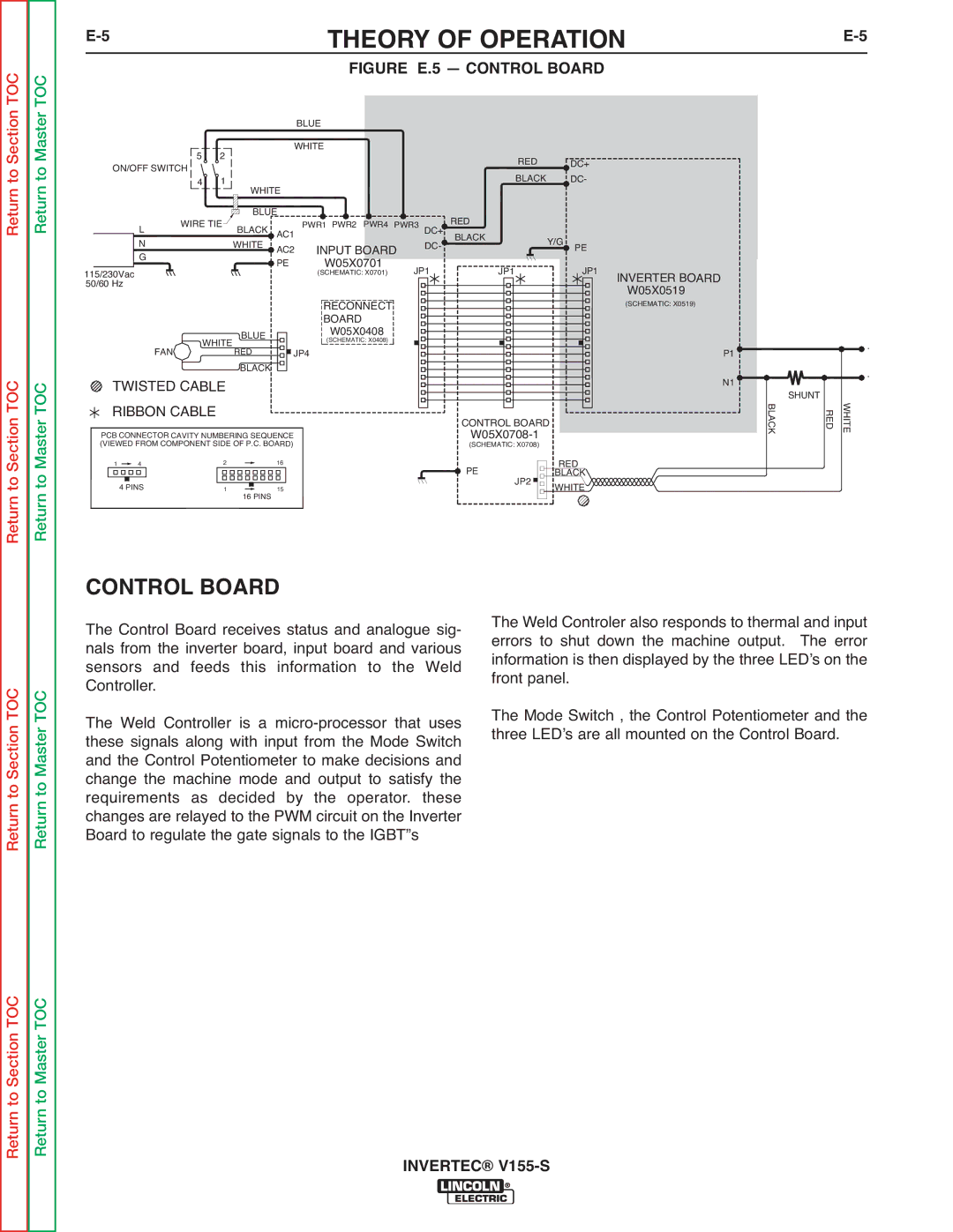
CONTROL BOARD
The Control Board receives status and analogue sig- nals from the inverter board, input board and various sensors and feeds this information to the Weld Controller.
The Weld Controller is a
The Weld Controler also responds to thermal and input errors to shut down the machine output. The error information is then displayed by the three LEDʼs on the front panel.
The Mode Switch , the Control Potentiometer and the three LEDʼs are all mounted on the Control Board.
Return to Section TOC
Return to Master TOC