Return to Section TOC
Return to Section TOC
Return to Section TOC
Return to Section TOC
Return to Master TOC
Return to Master TOC
Return to Master TOC
Return to Master TOC
F-11 TROUBLESHOOTING & REPAIRF-11
INPUT FILTER CAPACITOR DISCHARGE PROCEDURE (CONTINUED)
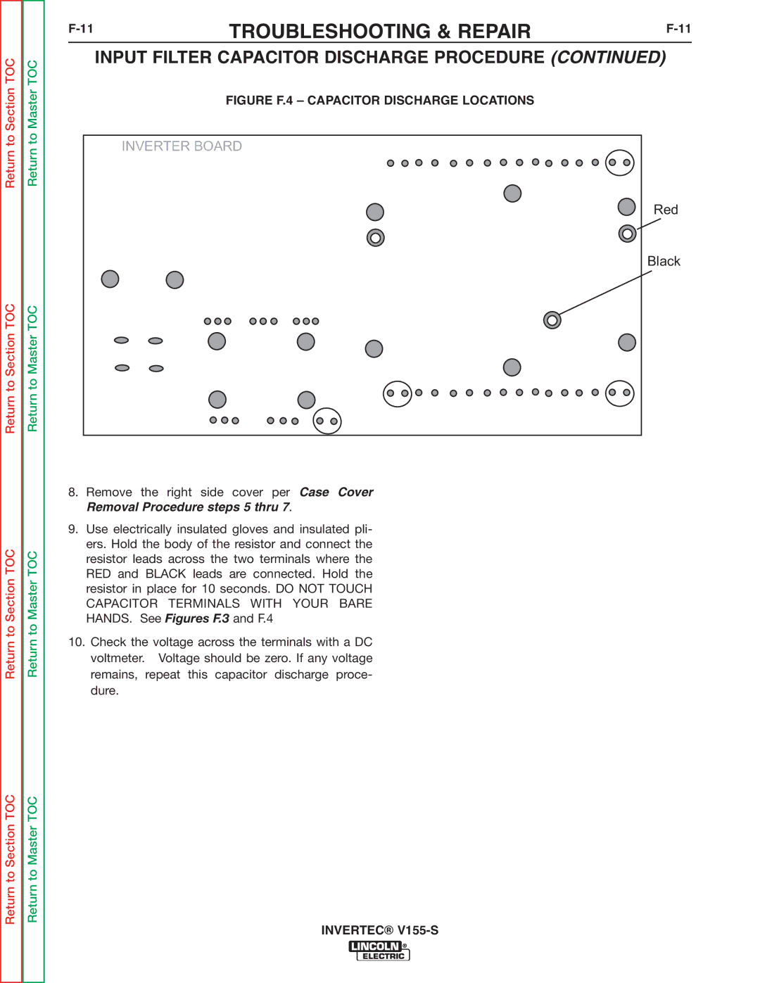
FIGURE F.4 – CAPACITOR DISCHARGE LOCATIONS
INVERTER BOARD
Red
Black
8.Remove the right side cover per Case Cover Removal Procedure steps 5 thru 7.
9.Use electrically insulated gloves and insulated pli- ers. Hold the body of the resistor and connect the resistor leads across the two terminals where the RED and BLACK leads are connected. Hold the resistor in place for 10 seconds. DO NOT TOUCH CAPACITOR TERMINALS WITH YOUR BARE HANDS. See Figures F.3 and F.4
10.Check the voltage across the terminals with a DC voltmeter. Voltage should be zero. If any voltage remains, repeat this capacitor discharge proce- dure.