Return to Section TOC
Return to Section TOC
Return to Master TOC
Return to Master TOC
F-29 TROUBLESHOOTING & REPAIRF-29
INVERTER BOARD REMOVAL AND REPLACEMENT PROCEDURE (CONTINUED)
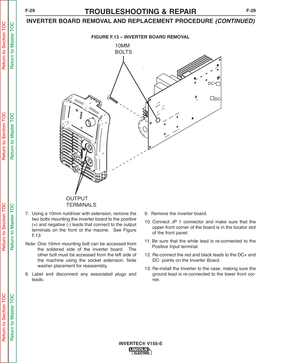
FIGURE F.13 – INVERTER BOARD REMOVAL
10MM
BOLTS
DC+![]()
![]() DC-
DC-
Return to Section TOC
Return to Master TOC
OUTPUT
TERMINALS
7. Using a 10mm nutdriver with extension, remove the two bolts mounting the inverter board to the positive
(+) and negative
Note: One 10mm mounting bolt can be accessed from the soldered side of the inverter board. The other bolt must be accessed from the left side of the machine using the socket extension. Note washer placement for reassembly,
8. Label and disconnect any associated plugs and leads.
9.Remove the inverter board.
10.Connect JP 1 connector and make sure that the upper front corner of the board is in the locator slot of the front panel.
11.Be sure that the white lead is
12.
13.
Return to Section TOC
Return to Master TOC