THEORY OF OPERATION | ||
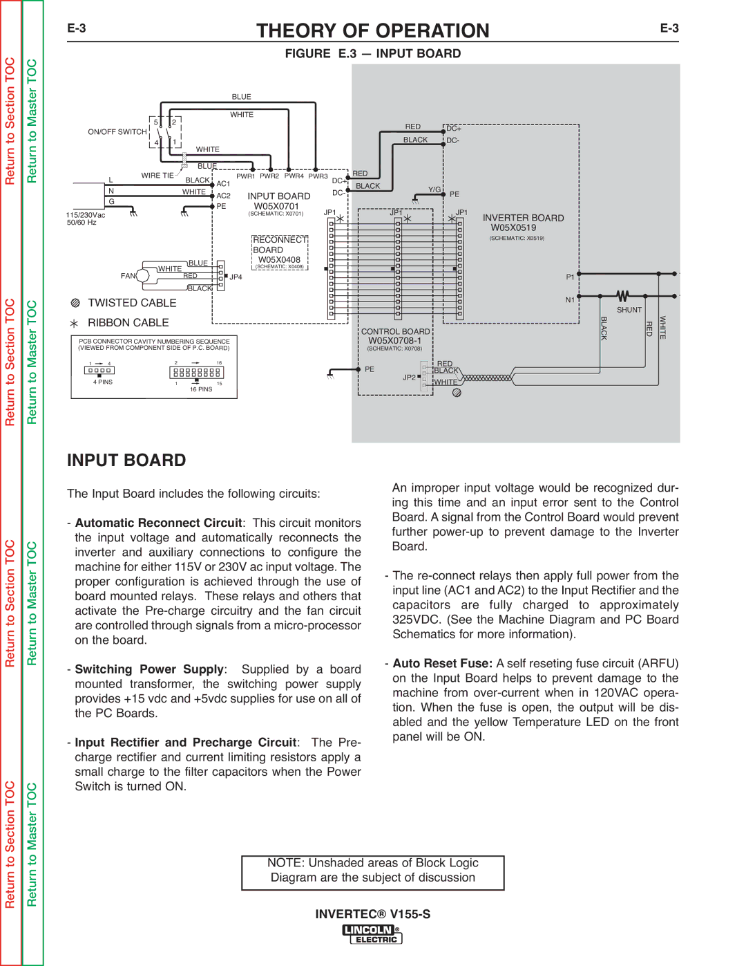
| FIGURE E.3 — INPUT BOARD |
|
Return to Master TOC
|
|
|
|
|
|
|
| BLUE |
| ON/OFF SWITCH | 5 | 2 |
| WHITE | |||
|
|
|
| |||||
| 4 | 1 | WHITE |
| ||||
|
|
|
|
| ||||
|
| L | WIRE TIE | BLUE | PWR1 PWR2 PWR4 PW | |||
|
| BLACK | AC1 | |||||
|
| N |
|
|
| WHITE | AC2 | INPUT BOARD |
|
| G |
|
|
|
| ||
115/230Vac |
|
|
|
| PE | W05X0701 | ||
|
|
|
|
|
| (SCHEMATIC: X0701) | ||
50/60 | Hz |
|
|
|
|
|
| RECONNECT |
|
|
|
|
|
|
|
| BOARD |
|
|
|
|
|
| BLUE |
| W05X0408 |
R3 | DC+ |
| DC- |
JP1 | |
RED BLACK
RED |
| DC+ |
|
BLACK |
| DC- |
|
JP1 | Y/G | PE |
|
| JP1 | INVERTER BOARD | |
|
|
| W05X0519 |
|
|
| (SCHEMATIC: X0519) |
Return to Master TOC
|
| FAN | WHITE | RED |
| JP4 | (SCHEMATIC: X0408) |
|
|
|
| ||||
TWISTED CABLE | BLACK |
|
| ||||
|
|
| |||||
|
|
|
| ||||
RIBBON CABLE |
|
|
|
| |||
PCB CONNECTOR CAVITY NUMBERING SEQUENCE |
| ||||||
(VIEWED FROM COMPONENT SIDE OF P.C. BOARD) |
|
| |||||
1 | 4 |
| 2 |
| 16 |
|
|
| 4 PINS |
| 1 | 16 PINS | 15 |
|
|
|
|
|
|
|
|
| |
CONTROL BOARD | |
(SCHEMATIC: X0708) | |
PE | JP2 |
| |
P1 ![]()
![]()
![]()
![]()
![]()
![]()
![]()
N1 ![]()
![]()
![]()
![]()
![]()
![]()
![]()
![]()
![]()
![]()
![]()
![]()
![]()
![]()
RED
BLACK
WHITE![]()
![]()
![]()
![]()
![]()
![]()
![]()
![]()
![]()
![]()
![]()
![]()
SHUNT | - | |
WHITE | ||
BLACK | ||
| RED |
Return to Section TOC
Return to Section TOC
Return to Section TOC
Section TOC
Return to Master TOC
Master TOC
INPUT BOARD
The Input Board includes the following circuits:
- Automatic Reconnect Circuit: This circuit monitors the input voltage and automatically reconnects the inverter and auxiliary connections to configure the machine for either 115V or 230V ac input voltage. The proper configuration is achieved through the use of board mounted relays. These relays and others that activate the
- Switching Power Supply: Supplied by a board mounted transformer, the switching power supply provides +15 vdc and +5vdc supplies for use on all of the PC Boards.
- Input Rectifier and Precharge Circuit: The Pre- charge rectifier and current limiting resistors apply a small charge to the filter capacitors when the Power Switch is turned ON.
An improper input voltage would be recognized dur- ing this time and an input error sent to the Control Board. A signal from the Control Board would prevent further
- The
-A self reseting fuse circuit (ARFU) onAutotheResetInputFuse:Board helps to prevent damage to the machine from
Return to
Return to
NOTE: Unshaded areas of Block Logic Diagram are the subject of discussion