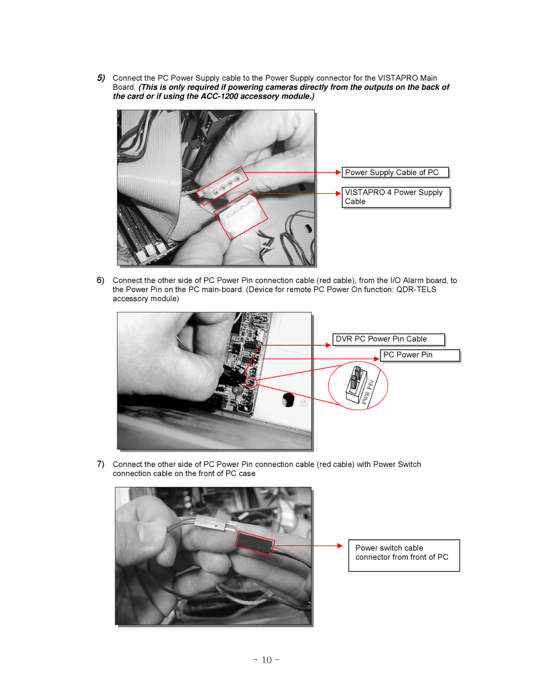
5)Connect the PC Power Supply cable to the Power Supply connector for the VISTAPRO Main Board. (This is only required if powering cameras directly from the outputs on the back of the card or if using the
![]()
![]() Power
Power![]() Supply Cable of
Supply Cable of![]() PC
PC![]()
![]()
![]()
![]() VISTAPRO
VISTAPRO![]() 4
4![]() Power
Power![]() Supply
Supply![]()
![]()
Cable![]()
![]()
![]()
![]()
![]()
![]()
![]()
![]()
![]()
![]()
![]()
![]()
![]()
![]()
6)Connect the other side of PC Power Pin connection cable (red cable), from the I/O Alarm board, to the Power Pin on the PC
DVR![]() PC
PC![]() Power Pin Cable
Power Pin Cable![]()
![]()
![]()
![]()
PC Power Pin
7)Connect the other side of PC Power Pin connection cable (red cable) with Power Switch connection cable on the front of PC case
Power switch cable connector from front of PC
- 10 -