P 3/ 37
 Repair
CAUTION: Unplug the tool and remove the saw blade from the machine for safety before repair/ maintenance in accordance with the instruction manual!
[1] NECESSARY REPAIRING TOOLS
| Code No. | Description | Use for |
|
|
|
|
|
|
| 1R028 | Bearing setting pipe | Mounting Retaining ring |
|
|
|
|
|
|
| 1R031 | Bearing setting pipe | Mounting Helical gear 27 |
|
|
|
|
|
|
| 1R034 | Bearing setting plate 12.2 | Mounting Helical gear 27 |
|
|
|
|
|
|
| 1R036 | Bearing setting plate 17.2 | Mounting Helical gear 28 |
|
|
|
|
|
|
| 1R045 | Gear extractor (large) | Mounting / Removing Helical gear 14 |
|
|
|
|
|
|
| 1R207 | Adjusting the bevel angle of Saw blade to 45 degree |
| |
|
|
|
|
|
| 1R208 | Adjusting the bevel angle of Saw blade to 90 degree |
| |
|
|
|
|
|
| 1R217 | Ring 22 | Removing Helical gear 27 |
|
| 1R220 | Ratchet head 27 | Attachment for 1R254 |
|
|
|
|
|
|
| 1R222 | Socket adapter | Attachment for 1R254 |
|
|
|
|
|
|
| 1R232 | Pipe 30 | Mounting Helical gear 28 |
|
|
|
|
|
|
| 1R254 | Torque wrench shaft 2 - 6 N.m | Tightening Hex lock nut |
|
|
|
|
|
|
| 1R269 | Bearing extractor (small) | Removing Ball bearings |
|
|
|
|
|
|
| 1R291 | Retaining ring S and R pliers | Removing Retaining ring in Gear section |
|
|
|
|
|
|
| 1R315 | Laser beam positioning jig | Adjusting Laser beam |
|
|
|
|
|
|
| 1R346 | Center attachment | Attachment for 1R045 |
|
|
|
|
|
|
| 1R361 | Bearing retainer wrench | Mounting / Removing Bearing retainer wrench |
|
|
|
|
| |
Flat washer 16 | Adjusting Laser beam |
| ||
|
|
|
| |
Socket | Attachment for 1R254 |
| ||
Box wrench 13 (standard accessory) | Installing /Removing Blade Adjusting Blade position |
| ||
|
|
|
|
|
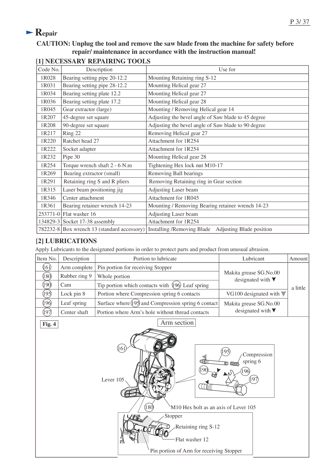
[2] LUBRICATIONS
Apply Lubricants to the designated portions in order to protect parts and product from unusual abrasion.
Item No. | Description | Portion to lubricate | Lubricant | Amount | |
|
|
|
|
| |
161 | Arm complete | Pin portion for receiving Stopper | Makita grease SG.No.00 |
| |
|
|
|
| ||
180 | Rubber ring 9 | Whole portion |
| ||
designated with |
| ||||
|
|
|
| ||
190 | Cam | Tip portion which contacts with 196 Leaf spring | a little | ||
| |||||
|
|
|
| ||
195 | Lock pin 8 | Portion where Compression spring 6 contacts | VG100 designated with | ||
| |||||
|
|
|
|
| |
196 | Leaf spring | Surface where 195 and Compression spring 6 contact | Makita grease SG.No.00 |
| |
197 | Center shaft | Portion where Arm’s hole without thread contacts | designated with |
| |
|
|
|
|
|
Fig. 4
Arm section
161 |
| 195 | Compression |
|
| ||
|
|
| |
|
|
| spring 6 |
| 190 |
| 196 |
Lever 105 |
|
| 197 |
180 | M10 Hex bolt as an axis of Lever 105 | ||
| Stopper |
|
|
| Retaining ring |
|
|
| Flat washer 12 |
|
|
Pin portion of Arm for receiving Stopper