P 8/ 37
 Repair
[3] DISASSEMBLY/ASSEMBLY
[3]-1. Blade case, Motor section (cont.)
DISASSEMBLING
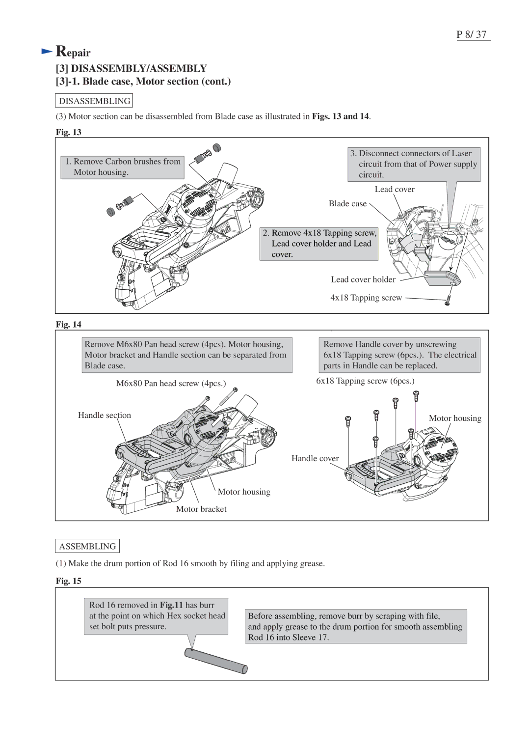
(3)Motor section can be disassembled from Blade case as illustrated in Figs. 13 and 14.
Fig. 13
1.Remove Carbon brushes from Motor housing.
3.Disconnect connectors of Laser circuit from that of Power supply circuit.
Lead cover
Blade case
2. Remove 4x18 Tapping screw, Lead cover holder and Lead cover.
Lead cover holder
4x18 Tapping screw ![]()
![]()
Fig. 14
Remove M6x80 Pan head screw (4pcs). Motor housing, Motor bracket and Handle section can be separated from Blade case.
M6x80 Pan head screw (4pcs.)
Handle section
![]() Motor housing
Motor housing
Motor bracket
Remove Handle cover by unscrewing
6x18 Tapping screw (6pcs.). The electrical parts in Handle can be replaced.
6x18 Tapping screw (6pcs.)
Motor housing
Handle cover
ASSEMBLING
(1) Make the drum portion of Rod 16 smooth by filing and applying grease.
Fig. 15
Rod 16 removed in Fig.11 has burr
at the point on which Hex socket head set bolt puts pressure.
Before assembling, remove burr by scraping with file,
and apply grease to the drum portion for smooth assembling Rod 16 into Sleeve 17.