RS-232C control
Connect a male
•The
•The PMD570 automatically transmits status data when status is changed.
•The PMD570 will respond to status requests by transmitting the associated status data.
RS-232C specifications:
Connector pin assignment | 1 | 2 | 3 | 4 | 5 |
|
| ||||||||||||||||
|
|
|
|
|
|
|
|
|
|
|
|
|
|
|
| 6 | 7 | 8 | 9 |
|
|
|
|
| pin | use |
|
|
|
| PMD570 |
| Typical Host | ||||||||||||||
|
|
|
| ||||||||||||||||||||
| 1 | NC |
|
| Not Connected |
| Not Connected | ||||||||||||||||
| 2 | TX |
|
| Transmit Data |
| Receive Data | ||||||||||||||||
| 3 | RX |
|
| Receive Data |
| Transmit Data | ||||||||||||||||
| 4 | NC |
|
| Not Connected |
| Not Connected | ||||||||||||||||
| 5 | GND |
|
|
|
|
| Ground |
| Ground |
|
|
|
|
| ||||||||
| 6 | NC |
|
| Not connected |
| Not connected | ||||||||||||||||
| 7 | RTS |
|
| RTS receive |
| RTS send | ||||||||||||||||
| 8 | CTS |
|
|
| CTS send |
| CTS receive | |||||||||||||||
| 9 | NC |
|
| Not Connected |
| Not Connected | ||||||||||||||||
| cable |
|
|
| |||||||||||||||||||
| connector |
|
|
|
|
| (male) |
| (female) | ||||||||||||||
Physical specifications |
|
|
|
|
|
|
|
|
|
| |||||||||||||
|
|
|
|
|
|
|
|
|
|
|
|
|
|
|
|
|
|
|
|
| |||
|
|
| Cable |
|
|
| Straight cable |
|
|
|
|
|
|
|
| ||||||||
|
|
|
|
|
|
|
|
|
|
|
|
|
|
|
|
|
|
|
|
|
| ||
|
|
| Baud rate |
|
|
| 9600 bps |
|
|
|
|
|
|
|
|
|
| ||||||
|
|
|
|
|
|
|
|
|
|
|
|
|
|
|
|
|
|
|
|
|
| ||
|
|
| Data bits |
|
|
| 8 bits |
|
|
|
|
|
|
|
|
|
| ||||||
|
|
|
|
|
|
|
|
|
|
|
|
|
|
|
|
|
|
|
|
|
| ||
|
|
| Parity bit |
|
|
| None |
|
|
|
|
|
|
|
|
|
| ||||||
|
|
|
|
|
|
|
|
|
|
|
|
|
|
|
|
|
|
|
|
|
| ||
|
|
| Stop bit |
|
|
| 1 bit |
|
|
|
|
|
|
|
|
|
| ||||||
|
|
|
|
|
|
|
|
|
|
|
|
|
|
|
|
| |||||||
|
|
| Flow control |
|
|
| CTS/RTS Hardware Flow |
|
| ||||||||||||||
|
|
|
|
|
|
|
|
|
|
|
|
|
|
|
|
|
|
|
| ||||
Flow control and timing |
|
|
|
|
|
|
|
|
|
| |||||||||||||
CTS/RTS hardware flow control |
|
|
|
|
|
|
|
|
|
| |||||||||||||
|
|
|
|
|
|
|
|
|
|
|
|
|
|
|
|
|
|
|
|
| |||
|
|
|
|
|
|
| Typical Host |
| PMD570 |
|
|
|
|
|
| ||||||||
|
|
|
|
|
|
| RTS send |
| CTS out |
|
|
|
|
|
| ||||||||
|
|
| Not Busy |
| H |
|
|
|
|
|
|
|
|
|
|
|
|
| |||||
|
|
|
|
|
|
|
|
|
|
|
|
|
|
|
|
| |||||||
|
|
|
|
|
|
|
|
|
|
|
|
|
|
|
|
|
|
|
|
| |||
|
|
| (Normal) |
| L |
|
|
|
|
|
|
|
|
|
|
|
|
|
|
| |||
|
|
|
|
|
|
|
|
|
|
|
|
|
|
|
|
|
|
|
|
|
| ||
|
|
|
|
|
|
|
|
|
|
|
|
|
|
|
|
|
|
|
|
|
|
| |
|
|
|
| Busy |
| H |
|
|
|
|
|
|
|
|
|
|
|
|
| ||||
|
|
|
|
|
|
|
|
|
|
|
|
|
|
|
|
| |||||||
|
|
|
|
|
|
|
|
|
|
|
|
|
|
|
|
|
|
|
|
|
| ||
|
|
|
|
|
|
| L |
|
|
|
|
|
|
|
|
|
|
|
| ||||
|
|
|
|
|
|
|
|
|
|
|
|
|
|
|
|
|
| ||||||
|
|
|
|
|
|
|
|
|
|
|
|
|
|
|
|
|
|
|
|
|
|
|
|
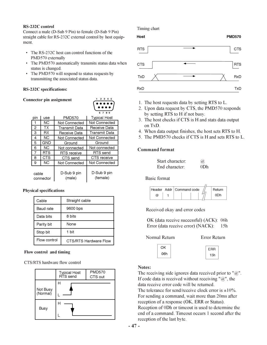
Timing chart
Host |
|
| PMD570 | |||
|
|
|
|
| CTS | |
RTS |
|
|
| |||
|
|
| ||||
|
|
|
|
|
|
|
CTS |
|
|
| RTS | ||
TxD |
|
|
| RxD | ||
|
|
| ||||
RxD |
|
|
| TxD | ||
|
|
|
|
|
|
|
1.The host requests data by setting RTS to L.
2.Upon data request by CTS, the PMD570 responds by setting RTS to H if not busy.
3.The host checks if CTS is H and stats data output on TxD.
4.When data output finishes, the host sets RTS to H.
5.The PMD570 checks if CTS is H and sets RTS to L.
Command format |
|
| |||||
Start character: | @ |
| |||||
End character: | 0Dh | ||||||
Basic format |
|
| |||||
|
|
|
|
|
|
| |
Header | Addr | Command code |
| Return | |||
@ |
|
|
|
|
|
| 0Dh |
1 |
|
|
|
|
| ||
|
|
|
|
|
|
|
|
Received okay and error codes
OK (data receive successful) (ACK): 06h
Error (data receive error) (NACK): 15h
Normal Return | Error Return | ||||
|
|
|
|
|
|
| OK |
|
|
|
|
|
|
| ERR |
| |
|
|
|
|
| |
| 06h |
|
| 15h |
|
|
|
|
|
| |
|
|
|
|
|
|
|
|
|
|
|
|
Notes:
The receiving side ignores data received prior to "@". If code data is received without receiving "@", the data receive error code will be returned.
The tolerance for send/receive clock error is ±10%. For sending a command, wait more than 20ms after reception of a response (OK, ERR or Status).
Reception of 0Dh or timeout is used to determine the end of a command. Timeout occurs 1 second after the reception of the last byte.
- 47 -