1.3.2 Rear View
25 | 26 | 27 | 28 |
IN
OUT
IN
| |
75 | SD Card |
|
OUT
ETHERNET
MONITOR AUDIO
ALARM I/O | DC12V |
|
29 30 31 32
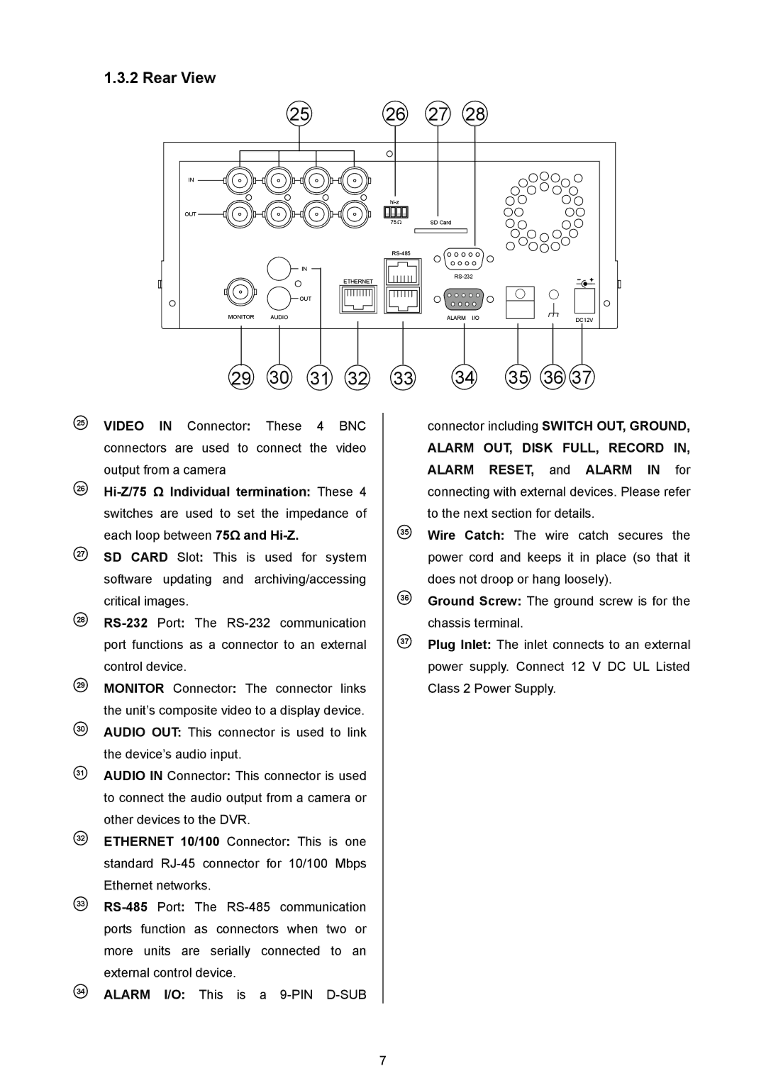
25 VIDEO IN Connector: These 4 BNC connectors are used to connect the video output from a camera
26
27SD CARD Slot: This is used for system software updating and archiving/accessing critical images.
28
29MONITOR Connector: The connector links the unit’s composite video to a display device.
30AUDIO OUT: This connector is used to link the device’s audio input.
31AUDIO IN Connector: This connector is used to connect the audio output from a camera or other devices to the DVR.
32ETHERNET 10/100 Connector: This is one standard
33
34ALARM I/O: This is a
33 | 34 | 35 | 36 37 |
connector including SWITCH OUT, GROUND,
ALARM OUT, DISK FULL, RECORD IN,
ALARM RESET, and ALARM IN for connecting with external devices. Please refer to the next section for details.
35Wire Catch: The wire catch secures the power cord and keeps it in place (so that it does not droop or hang loosely).
36Ground Screw: The ground screw is for the chassis terminal.
37Plug Inlet: The inlet connects to an external power supply. Connect 12 V DC UL Listed Class 2 Power Supply.
7