
RFS, RCS, RCS10DA specifications
The Maytag RCS10DA, RCS, and RFS series are some of the most innovative and reliable appliances in the modern kitchen. With a focus on performance, efficiency, and user convenience, these models stand out in the crowded market of refrigerators and freezers.The Maytag RCS10DA is designed to deliver outstanding cooling performance while keeping energy consumption in check. One of its standout features is the Twin Cooling System, which uses two separate airflow systems to maintain optimal humidity levels in both the refrigerator and freezer sections. This technology ensures that your foods stay fresher for longer by preventing the mixing of odors and moisture.
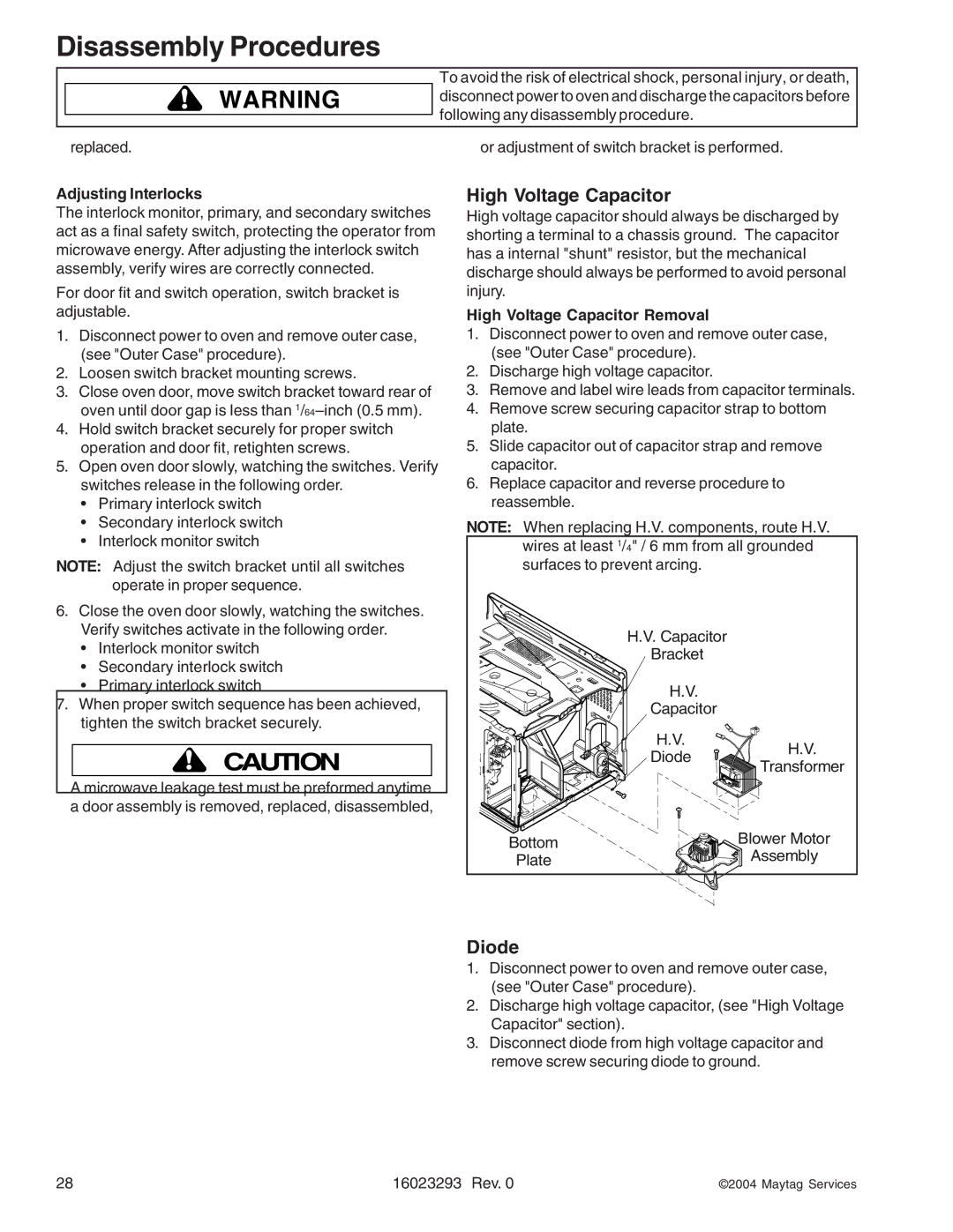
In addition to Twin Cooling, the RCS series is equipped with the PowerCold feature. This function is particularly helpful for quickly chilling items after grocery shopping or hosting large gatherings. With a simple press of a button, the refrigerator rapidly cools down to the desired temperature, ensuring that perishable items remain safe and fresh.
The RCS and RFS models boast adjustable shelving and organizational bins that provide maximum storage flexibility. The shelves are designed to accommodate taller items, and the door bins are deep enough to hold larger bottles and containers. Furthermore, these models feature LED interior lighting that not only enhances visibility but also consumes less energy compared to traditional bulbs.
Durability is another hallmark of Maytag appliances, and the RCS series is no exception. Constructed with heavy-duty materials and a robust design, these refrigerators are built to withstand the rigors of daily use. Additionally, many models come with a stainless steel finish that resists fingerprints and makes cleaning a breeze.
Energy efficiency is a critical aspect of modern appliances, and Maytag addresses this with Energy Star certification. The RCS and RFS models are designed to use less energy without compromising performance, thereby reducing utility bills and environmental impact.
In summary, the Maytag RCS10DA, RCS, and RFS series offer a suite of features and technologies that cater to the needs of today’s consumers. With innovations like the Twin Cooling System, PowerCold feature, adjustable shelving, and a commitment to durability and energy efficiency, these models are ideal choices for anyone looking to elevate their kitchen experience. Whether you require expansive storage or quick cooling solutions, Maytag provides reliable appliances designed to meet modern demands.