2. Installation
See section 6.1 for information on sizing protection devices and cables (Appendix, Technical data).
A maximum of four cables may be used per phase.
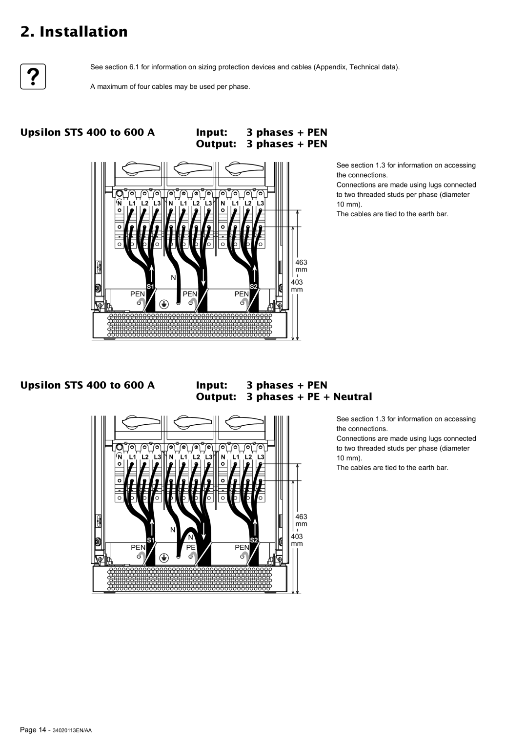
Upsilon STS 400 to 600 A | Input: 3 phases + PEN |
| Output: 3 phases + PEN |
N L1 L2 L3![]()
![]() N L1 L2 L3
N L1 L2 L3![]()
![]() N L1 L2 L3
N L1 L2 L3
See section 1.3 for information on accessing the connections.
Connections are made using lugs connected to two threaded studs per phase (diameter 10 mm).
The cables are tied to the earth bar.
|
|
| 463 | |
|
|
| mm | |
| N |
| 403 | |
| S1 | S2 | ||
| mm | |||
PEN | PEN | PEN | ||
|
Upsilon STS 400 to 600 A | Input: | 3 phases + PEN |
| Output: | 3 phases + PE + Neutral |
N L1 L2 L3
N L1 L2 L3
N L1 L2 L3
See section 1.3 for information on accessing the connections.
Connections are made using lugs connected to two threaded studs per phase (diameter 10 mm).
The cables are tied to the earth bar.
|
|
|
|
| 463 |
|
| N |
|
| mm |
|
|
|
| 403 | |
| S1 | N |
| S2 | |
|
|
| mm | ||
PEN |
| PE | PEN |
| |
|
|
|
Page 14 - 34020113EN/AA