2.Installation
2.6Connection of the relay communication card
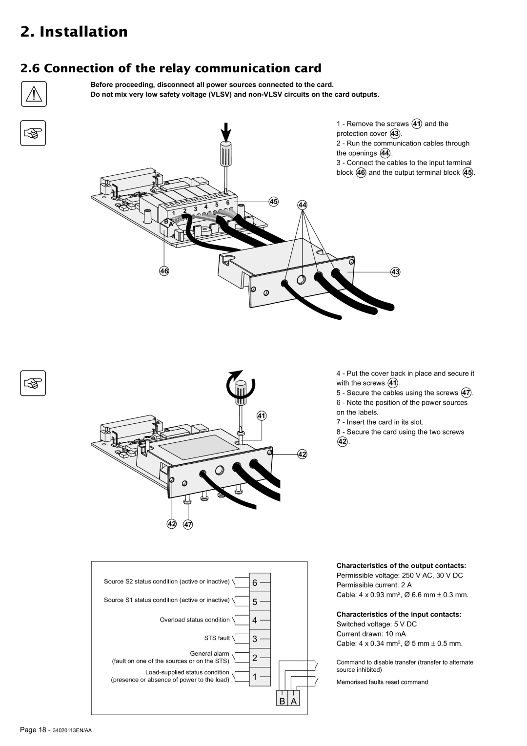
Before proceeding, disconnect all power sources connected to the card.
Do not mix very low safety voltage (VLSV) and
1 - Remove the screws 41 and the protection cover 43 .
2 - Run the communication cables through the openings 44 .
3 - Connect the cables to the input terminal block 46 and the output terminal block 45 .
|
|
| 4 | 5 | 6 | 45 | 44 |
| 2 | 3 |
|
| |||
1 |
|
|
|
|
| ||
|
|
|
|
|
| ||
|
|
|
|
|
|
| |
BA |
|
|
|
|
|
|
|
46 |
|
|
|
|
|
| 43 |
41
42 47
Source S2 status condition (active or inactive) | 6 |
|
| ||
|
| |
Source S1 status condition (active or inactive) |
|
|
5 |
| |
|
| |
|
|
|
Overload status condition | 4 |
|
| ||
|
|
|
STS fault | 3 |
|
| ||
General alarm |
|
|
2 |
| |
(fault on one of the sources or on the STS) |
| |
|
| |
|
| |
1 |
| |
(presence or absence of power to the load) |
| |
|
|
|
4 - Put the cover back in place and secure it with the screws 41 .
5 - Secure the cables using the screws 47 . 6 - Note the position of the power sources on the labels.
7 - Insert the card in its slot.
8 - Secure the card using the two screws
42.
42
Characteristics of the output contacts:
Permissible voltage: 250 V AC, 30 V DC
Permissible current: 2 A
Cable: 4 x 0.93 mm2, Ø 6.6 mm ± 0.3 mm.
Characteristics of the input contacts:
Switched voltage: 5 V DC
Current drawn: 10 mA
Cable: 4 x 0.34 mm2, Ø 5 mm ± 0.5 mm.
Command to disable transfer (transfer to alternate source inhibited)
Memorised faults reset command
B A
Page 18 - 34020113EN/AA