1. Presentation
1.3 Access to control and connections
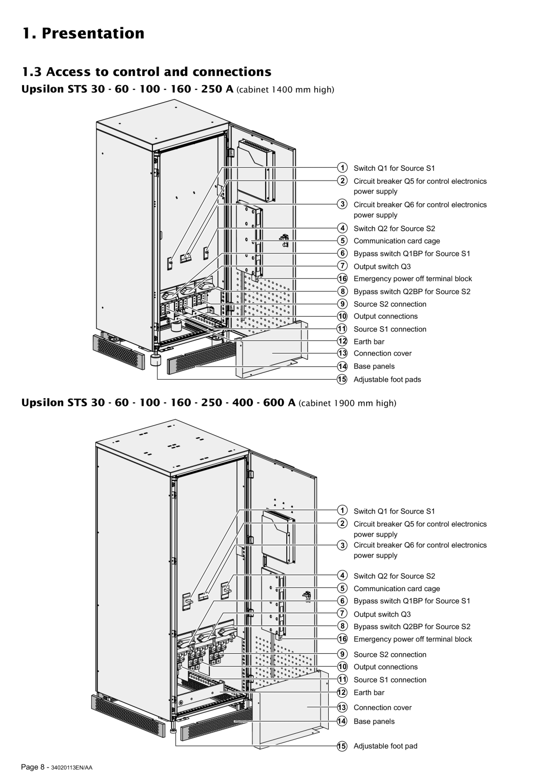
Upsilon STS 30 - 60 - 100 - 160 - 250 A (cabinet 1400 mm high)
1 Switch Q1 for Source S1
2 Circuit breaker Q5 for control electronics power supply
3 Circuit breaker Q6 for control electronics power supply
4 Switch Q2 for Source S2
5 Communication card cage
6 Bypass switch Q1BP for Source S1
7 Output switch Q3
16 Emergency power off terminal block
8 Bypass switch Q2BP for Source S2
9 Source S2 connection
10 Output connections
11 Source S1 connection
12 Earth bar
13 Connection cover
14 Base panels
15 Adjustable foot pads
Upsilon STS 30 - 60 - 100 - 160 - 250 - 400 - 600 A (cabinet 1900 mm high)
1 | Switch Q1 for Source S1 |
2 | Circuit breaker Q5 for control electronics |
| power supply |
3 | Circuit breaker Q6 for control electronics |
| power supply |
4 | Switch Q2 for Source S2 |
5 | Communication card cage |
6 | Bypass switch Q1BP for Source S1 |
7 | Output switch Q3 |
8 | Bypass switch Q2BP for Source S2 |
16 | Emergency power off terminal block |
9 | Source S2 connection |
10 | Output connections |
11 | Source S1 connection |
12 | Earth bar |
13 | Connection cover |
14 | Base panels |
15 | Adjustable foot pad |
Page 8 - 34020113EN/AA