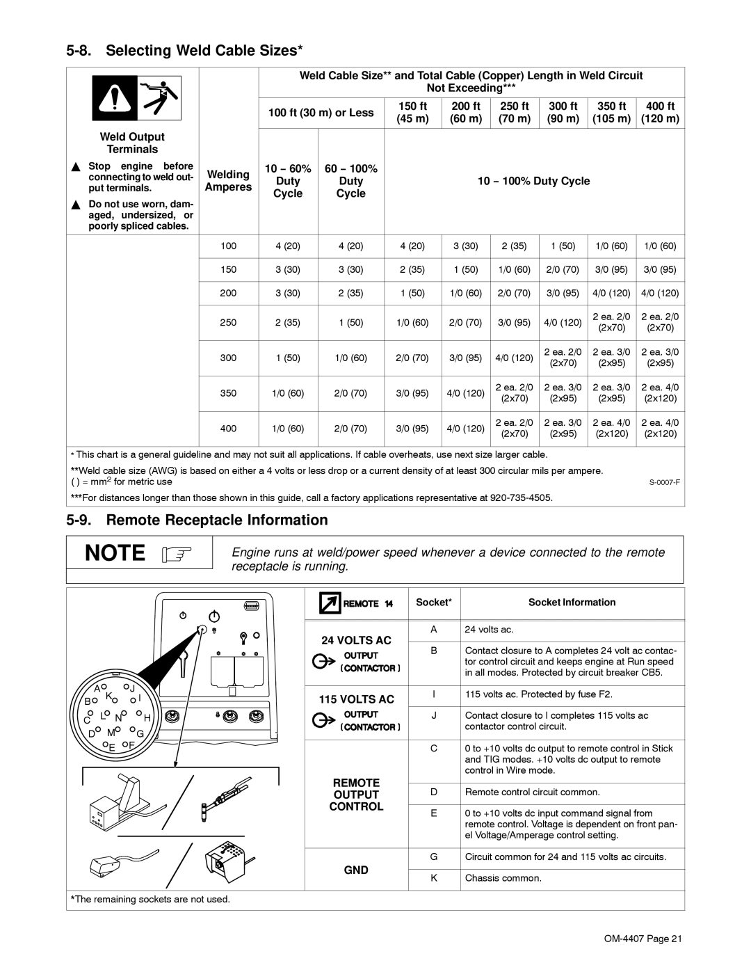
5-8. Selecting Weld Cable Sizes*
|
|
|
|
| Weld Cable Size** and Total Cable (Copper) Length in Weld Circuit | ||||||||
|
|
|
|
| |||||||||
|
|
|
|
|
|
| Not Exceeding*** |
|
|
|
| ||
|
|
|
|
|
|
|
|
|
|
|
|
|
|
|
|
|
|
| 100 ft (30 m) or Less | 150 ft | 200 ft | 250 ft | 300 ft |
| 350 ft | 400 ft | |
|
|
|
|
| (45 m) | (60 m) | (70 m) | (90 m) |
| (105 m) | (120 m) | ||
| Weld Output |
|
|
|
| ||||||||
|
|
|
|
|
|
|
|
|
|
| |||
|
|
|
|
|
|
|
|
|
|
| |||
| Terminals |
|
|
|
|
|
|
|
|
|
| ||
Y Stop engine before | Welding | 10 − 60% | 60 − 100% |
|
|
|
|
|
|
| |||
connecting to weld out- | Duty | Duty |
| 10 − 100% Duty Cycle |
|
| |||||||
put terminals. | Amperes |
|
|
| |||||||||
Cycle | Cycle |
|
|
|
|
|
|
| |||||
|
|
|
|
|
|
|
|
|
|
|
| ||
YDo not use worn, dam- aged, undersized, or poorly spliced cables.
100 | 4 (20) | 4 (20) | 4 (20) | 3 (30) | 2 (35) | 1 (50) | 1/0 (60) | 1/0 (60) | ||
|
|
|
|
|
|
|
|
|
| |
150 | 3 (30) | 3 (30) | 2 (35) | 1 (50) | 1/0 (60) | 2/0 (70) | 3/0 (95) | 3/0 (95) | ||
|
|
|
|
|
|
|
|
|
| |
200 | 3 (30) | 2 (35) | 1 (50) | 1/0 (60) | 2/0 (70) | 3/0 (95) | 4/0 (120) | 4/0 (120) | ||
|
|
|
|
|
|
|
|
|
| |
250 | 2 (35) | 1 (50) | 1/0 (60) | 2/0 (70) | 3/0 (95) | 4/0 (120) | 2 ea. 2/0 | 2 ea. 2/0 | ||
(2x70) | (2x70) | |||||||||
|
|
|
|
|
|
|
| |||
|
|
|
|
|
|
|
|
|
| |
300 | 1 (50) | 1/0 (60) | 2/0 (70) | 3/0 (95) | 4/0 (120) | 2 ea. 2/0 | 2 ea. 3/0 | 2 ea. 3/0 | ||
(2x70) | (2x95) | (2x95) | ||||||||
|
|
|
|
|
|
| ||||
|
|
|
|
|
|
|
|
|
| |
350 | 1/0 (60) | 2/0 (70) | 3/0 (95) | 4/0 (120) | 2 ea. 2/0 | 2 ea. 3/0 | 2 ea. 3/0 | 2 ea. 4/0 | ||
(2x70) | (2x95) | (2x95) | (2x120) | |||||||
|
|
|
|
|
| |||||
|
|
|
|
|
|
|
|
|
| |
400 | 1/0 (60) | 2/0 (70) | 3/0 (95) | 4/0 (120) | 2 ea. 2/0 | 2 ea. 3/0 | 2 ea. 4/0 | 2 ea. 4/0 | ||
(2x70) | (2x95) | (2x120) | (2x120) | |||||||
|
|
|
|
|
| |||||
|
|
|
|
|
|
|
|
|
| |
*This chart is a general guideline and may not suit all applications. If cable overheats, use next size larger cable.
**Weld cable size (AWG) is based on either a 4 volts or less drop or a current density of at least 300 circular mils per ampere. |
|
( ) = mm2 for metric use |
***For distances longer than those shown in this guide, call a factory applications representative at
5-9. Remote Receptacle Information
NOTE
Engine runs at weld/power speed whenever a device connected to the remote receptacle is running.
|
|
|
|
| Socket* | Socket Information |
|
|
|
| 24 VOLTS AC | A | 24 volts ac. |
|
|
|
| B | Contact closure to A completes 24 volt ac contac- | |
|
|
|
|
| ||
|
|
|
|
|
| tor control circuit and keeps engine at Run speed |
|
|
|
|
|
| in all modes. Protected by circuit breaker CB5. |
A | K | J |
| I | 115 volts ac. Protected by fuse F2. | |
B |
| I | 115 VOLTS AC | |||
|
|
| ||||
C | L N | H |
| J | Contact closure to I completes 115 volts ac | |
D |
| M | G |
|
| contactor control circuit. |
|
|
|
| |||
|
| E | F |
| C | 0 to +10 volts dc output to remote control in Stick |
|
|
|
|
|
| and TIG modes. +10 volts dc output to remote |
|
|
|
|
|
| control in Wire mode. |
|
|
|
| REMOTE | D | Remote control circuit common. |
|
|
|
| OUTPUT | ||
|
|
|
| CONTROL | E | 0 to +10 volts dc input command signal from |
|
|
|
|
| ||
|
|
|
|
|
| remote control. Voltage is dependent on front pan- |
|
|
|
|
|
| el Voltage/Amperage control setting. |
|
|
|
|
| G | Circuit common for 24 and 115 volts ac circuits. |
|
|
|
| GND | K | Chassis common. |
|
|
|
|
| ||
*The remaining sockets are not used.