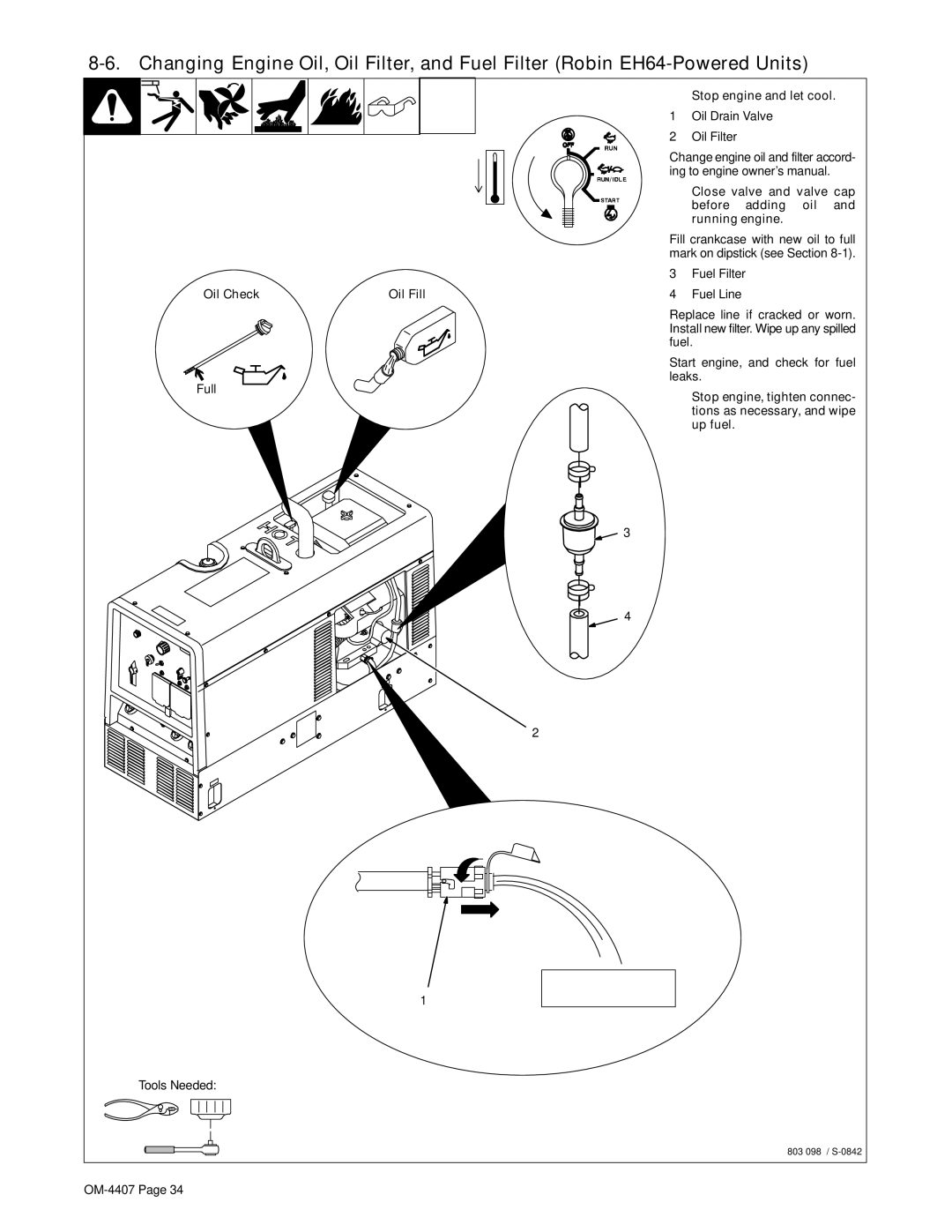
Main
Trailblazer 301 G Trailblazer DC
From Miller to You
Page
TABLE OF CONTENTS
OM-4407 Page 1
SECTION 1 SAFETY PRECAUTIONS READ BEFORE USING
Warning: Protect yourself and others from injury read and follow these precautions.
1-1. Symbol Usage
Marks a special safety message.
1-2. Arc Welding Hazards
1-3. Engine Hazards
BATTERY EXPLOSION can BLIND.
FUEL can cause fire or explosion.
MOVING PARTS can cause injury.
OM-4407 Page 3
1-4. Compressed Air Hazards
BREATHING COMPRESSED AIR can cause serious injury or death.
COMPRESSED AIR can cause injury.
TRAPPED AIR PRESSURE AND WHIPPING HOSES can cause injury.
HOT METAL from air arc cutting and gouging can cause fire or explosion.
1-6. California Proposition 65 Warnings
1-7. Principal Safety Standards
1-8. EMF Information
OM-4407 Page 5
SECTION 2 CONSIGNES DE SCURIT LIRE AVANT UTILISATION
Avertissement: Protgez vous et les autres des blessures lisez et suivez ces prcautions.
2-1. Signification des symboles
Identifie un message de scurit particulier.
2-2. Dangers relatifs au soudage larc
2-3. Dangers existant en relation avec le moteur
LES ACCUMULATIONS DE GAZ ris- quent de provoquer des blessures ou mme la mort.
LACIDE DE LA BATTERIE peut pro- voquer des brlures dans les YEUX et sur la PEAU.
OM-4407 Page 7
LEXPLOSION DE LA BATTERIE peut RENDRE AVEUGLE.
2-4. Dangers lis lair comprim
RESPIRER LAIR COMPRIM peut pro- voquer des blessures graves ou causer la mort.
LAIR COMPRIM peut provoquer des blessures.
LAIR COMPRIME EMMAGASINE ET DES TUYAUX SOUS PRESSION peuvent provo- quer des blessures.
Le METAL CHAUD lors du coupage et gougeage plasma peut provoquer un in- cendie ou une explosion.
2-6. Principales normes de scurit
2-7. Information sur les champs lectromagntiques
SECTION 3 DEFINITIONS
3-1. Symbol Definitions
Pros weld and cut safely. Read the safety rules at the beginning of this manual.
SECTION 4 SPECIFICATIONS
4-1. Weld, Power, And Engine Specifications
4-2. Dimensions, Weights, and Operating Angles
4-3. Fuel Consumption While Welding
DC WELD AMPERES AT 100% DUTY CYCLE
KW AT 100% DUTY CYCLE
US GAL/HR.
LITERS/HR.
4-5. Generator Power Curve
4-6. Duty Cycle
4-7. Stick And MIG Mode Volt-Ampere Curves
4-8. TIG Mode Volt-Ampere Curves
SECTION 5 INSTALLATION
5-1. Installing Welding Generator
5-2. Engine Prestart Checks (Robin EH64-Powered Units)
5-3. Engine Prestart Checks (Kohler-Powered Units)
5-4. Activating The Dry Charge Battery (If Applicable)
+
5-5. Connecting The Battery
+
5-6. Installing Exhaust Pipe
5-7. Connecting To Weld Output Terminals
5-8. Selecting Weld Cable Sizes*
5-9. Remote Receptacle Information
Engine runs at weld/power speed whenever a device connected to the remote receptacle is running.
NOTE
5-10. Adjusting Wire (MIG) Weld Puddle Consistency
SECTION 6 OPERATING WELDING GENERATOR
6-1. Front Panel Controls
6-2. Process/Contactor Switch On CC/CV Models
Process/Contactor Switch Settings
6-3. Remote Amperage/Voltage Control
(Stick Welding Only)
A/V Control Adjust Remote Control
Set V/A Adjust Switch Set
SECTION 7 OPERATING AUXILIARY EQUIPMENT
7-1. Generator Power Receptacles And Circuit Breakers
Page
7-3. Wiring Instructions For Optional 240 Volt, Single-Phase Plug (NEMA 14-50P)
Page
8-2. Routine Maintenance (Robin EH64-Powered Units)
Note
Every 8 h
Every 20 h Every 25 h
Every 50 h
Every 100 h
Every 200 h
Every 500 h
Every 1000 h
8-3. Servicing Air Cleaner (Robin EH64-Powered Units)
8-4. Servicing Optional Spark Arrestor (Robin EH64-Powered Units)
Tools Needed:
8-5. Overload Protection (Robin EH64-Powered Units)
8-6. Changing Engine Oil, Oil Filter, and Fuel Filter (Robin EH64-Powered Units)
8-7. Adjusting Engine Speed (Robin EH64-Powered Units)
SECTION 9 MAINTENANCE (KOHLER-POWERED UNITS)
9-1. Routine Maintenance (Kohler-Powered Units)
Every 8 h
Full
Every 20 h Every 25 h
Page
9-3. Servicing Air Cleaner (Kohler-Powered Units)
9-4. Servicing Optional Spark Arrestor (Kohler-Powered Units)
9-5. Changing Engine Oil, Oil Filter, And Fuel Filter (Kohler-Powered Units)
9-6. Adjusting Engine Speed (Kohler-Powered Units)
9-7. Overload Protection (Kohler-Powered Units)
SECTION 10 TROUBLESHOOTING
10-1. Welding Troubleshooting
10-2. Generator Power Troubleshooting
10-3. Engine Troubleshooting
Page
Page
Page
Page
Page
Page
SECTION 12 GENERATOR POWER GUIDELINES
NOTE
12-1. Selecting Equipment
12-2. Grounding Generator To Truck Or Trailer Frame
12-3. Grounding When Supplying Building Systems
12-4. How Much Power Does Equipment Require?
12-5. Approximate Power Requirements For Industrial Motors
12-6. Approximate Power Requirements For Farm/Home Equipment
12-7. Approximate Power Requirements For Contractor Equipment
12-8. Power Required To Start Motor
12-9. How Much Power Can Generator Supply?
12-10. Typical Connections To Supply Standby Power
Pros weld and cut safely. Read the safety rules at the beginning of this manual.
12-11. Selecting Extension Cord (Use Shortest Cord Possible)
Page
SECTION 13 PARTS LIST
Figure 13-1. Main Assembly (Kohler Engine Shown)
Page
Page
Page
Figure 13-2. Panel, Front w/Components
Page
Page
Page
Page
Warranty Questions?
Call 1-800-4-A-MILLER for your local Miller distributor.
Effective January 1, 2004 (Equipment with a serial number preface of LE or newer)
Please complete and retain with your personal records.
For Service
Always provide Model Name and Serial/Style Number.
Owners Record