2-10. Arc Failure Light Connections
Robot Control Unit | Robot Interface | |
Common Terminal |
| Weld Alarm Terminal |
If So Equipped | Signal | If So Equipped |
| Relay |
|
| CR | 1TL |
+24VDC |
|
|
|
|
| Arc Failure |
|
| 1TM | Indicator Light |
Robot Control Unit |
| ||
Common Terminal |
| Weld Alarm Terminal | |
If So Equipped | Signal | If So Equipped | |
| Relay |
|
|
| CR |
|
|
To Voltage Source
(115VAC, 24VAC, 24VDC)
Isolation Relay CR
Robot Control Unit | Robot Interface |
1TL
+24VDC
Isolation Relay CR
1TM | Arc Failure |
Indicator Light |
Tools Needed:
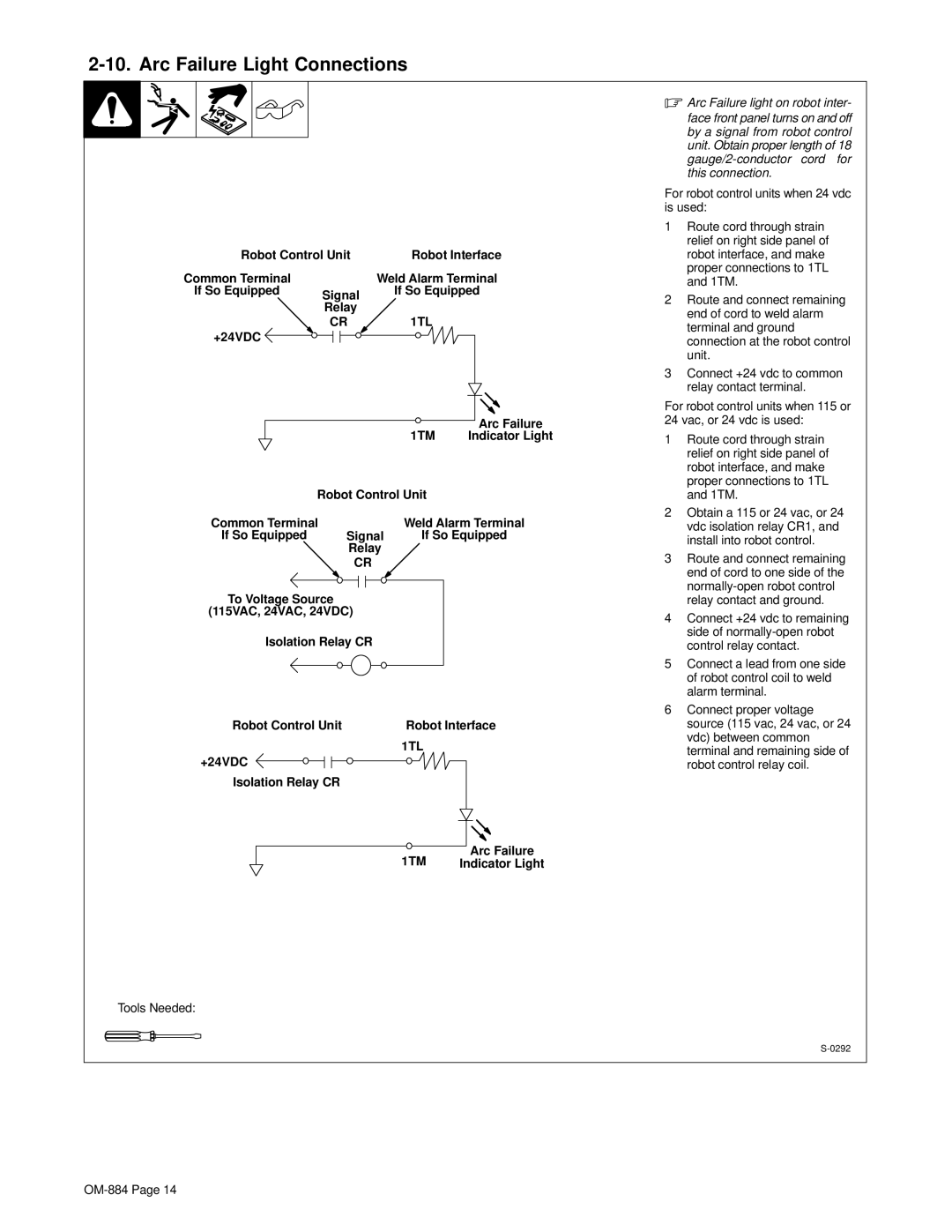
.Arc Failure light on robot inter- face front panel turns on and off by a signal from robot control unit. Obtain proper length of 18
For robot control units when 24 vdc is used:
1Route cord through strain relief on right side panel of robot interface, and make proper connections to 1TL and 1TM.
2Route and connect remaining end of cord to weld alarm terminal and ground connection at the robot control unit.
3Connect +24 vdc to common relay contact terminal.
For robot control units when 115 or
24 vac, or 24 vdc is used:
1Route cord through strain relief on right side panel of robot interface, and make proper connections to 1TL and 1TM.
2Obtain a 115 or 24 vac, or 24 vdc isolation relay CR1, and install into robot control.
3Route and connect remaining end of cord to one side of the
4Connect +24 vdc to remaining side of
5Connect a lead from one side of robot control coil to weld alarm terminal.
6Connect proper voltage source (115 vac, 24 vac, or 24 vdc) between common terminal and remaining side of robot control relay coil.