Manuals
/
Brands
/
Computer Equipment
/
Switch
/
Miller Electric
/
Computer Equipment
/
Switch
Miller Electric
A.B.B. Robot Interface Gas Control Hub And Spindle
- page 34
1
34
40
40
Download
40 pages, 866.02 Kb
OM-884 Page 30
1
2
3
4
5
6
7
8
9
10
11
12
13
14
15
16
17
18
19
20
21 22
23
24
25
26
12
.
Hardware is
common and
not available unless listed.
119 648-C
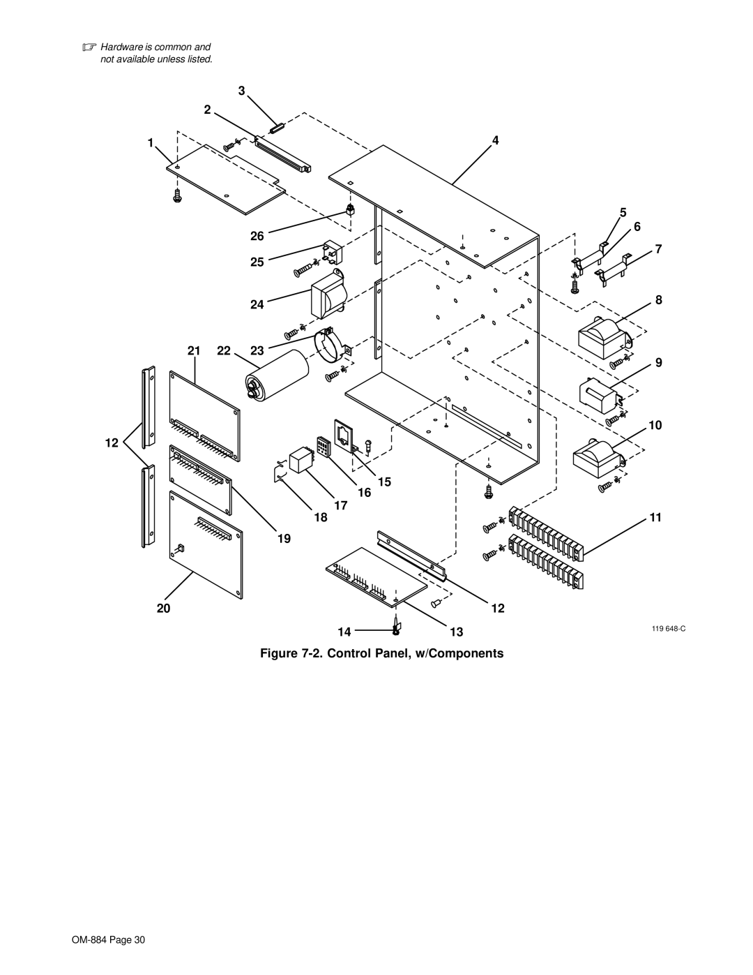
Figure 7-2. Control Panel, w/Components
Contents
Main
From Miller to You
TABLE OF CONTENTS
Page
SECTION 1 SAFETY PRECAUTIONS - READ BEFORE USING
1-1. Symbol Usage
.
1-2. Arc Welding Hazards
ELECTRIC SHOCK can kill.
ARC RAYS can burn eyes and skin.
WELDING can cause fire or explosion.
FLYING METAL can injure eyes.
BUILDUP OF GAS can injure or kill.
HOT PARTS can cause severe burns.
1-3. Additional Symbols For Installation, Operation, And Maintenance
FIRE OR EXPLOSION hazard.
FALLING UNIT can cause injury.
OVERUSE can cause OVERHEATING
STATIC (ESD) can damage PC boards.
1-5. EMF Information
OM-884 Page 5
SECTION 1 CONSIGNES DE SECURITE LIRE AVANT UTILISATION
1-1. Signification des symboles
.
1-2. Dangers relatifs au soudage larc
UN CHOC LECTRIQUE peut tuer.
LES RAYONS DE LARC peuvent pro- voquer des brlures dans les yeux et sur la peau.
LE SOUDAGE peut provoquer un incendie ou une explosion.
DES PARTICULES VOLANTES peuvent blesser les yeux.
LES ACCUMULATIONS DE GAZ ris- quent de provoquer des blessures ou mme la mort.
DES PICES CHAUDES peuvent pro- voquer des brlures graves.
1-3. Dangers supplmentaires en relation avec linstallation, le fonctionnement et la maintenance
1-4. Principales normes de scurit
1-5. Information sur les champs lectromagntiques
SECTION 2 INSTALLATION
2-1. Specifications
Dimensions Weight Component Height Width Depth Net Ship
Spool Support Assembly+
2-2. Mounting Hole Layout
2-3. Connection Diagram
2-4. Robot Interface Connections
2-5. Shielding Gas Connection To Regulator/Flowmeter
2-6. Shielding Gas Connections To Gas Control
2-7. Arc Sensing Connections
2-8. 14-Pin Receptacle RC13 Information
2-9. 24-Socket Receptacle RC17 Information
2-10. Arc Failure Light Connections
.
2-11. Matching Digital Voltage Control (DVC) Board To Welding Power Source
2-12. Hub Assembly Installation
2-13. Installing Spool-Type Wire And Adjusting Hub Tension
2-14. Installing Optional Reel-Type Wire
SECTION 3 OPERATION
3-1. Safety Equipment
3-2. Work Clamp
3-3. Front Panel Controls
3-4. Indicator Lights
3-5. Burnback Control
SECTION 4 SEQUENCE OF OPERATION
4-1. Input/Output Signals
SECTION 5 MAINTENANCE & TROUBLESHOOTING
5-1. Routine Maintenance
3 Months
6 Months
5-2. Replacing The Hub Assembly
5-3. Overload Protection
5-4. Display Board PC4 Meter Check
5-5. Troubleshooting
5-6. Use Of Indicator Lights For Troubleshooting
Page
SECTION 7 PARTS LIST
Page
Page
Page
Page
Page
Page
Warranty Questions?
Call 1-800-4-A-MILLER for your local Miller distributor.
Effective January 1, 2000 (Equipment with a serial number preface of LA or newer)
Please complete and retain with your personal records.
For Service
Always provide Model Name and Serial/Style Number.
Owners Record