SECTION 2 – INSTALLATION
2-1. Specifications
|
| Dimensions |
|
| Weight | |
|
|
|
|
|
|
|
Component | Height | Width | Depth | Net |
| Ship |
|
|
|
|
|
|
|
|
|
|
|
|
|
|
Robot Interface |
| 38 lbs. |
|
| ||
(572 mm) | (419 mm) | (159 mm) | (17 kg) |
|
| |
|
|
| ||||
|
|
|
|
|
|
|
Gas/Current | 5 lbs. |
| Total 61 lbs. | |||
Sensing Control | (108 mm) | (140 mm) | (267 mm) | (2.3 kg) |
| (27.7 kg) |
|
|
|
|
|
|
|
Spool Support | 6 lbs. |
|
| |||
Assembly+ | (349 mm) | (222 mm) | (216 mm) | (2.7 kg) |
|
|
|
|
|
|
|
| |
♦Add |
| +Spool Support without optional wire reel. | ||||
*Add 7/8 in. (22 mm) for front panel knob.
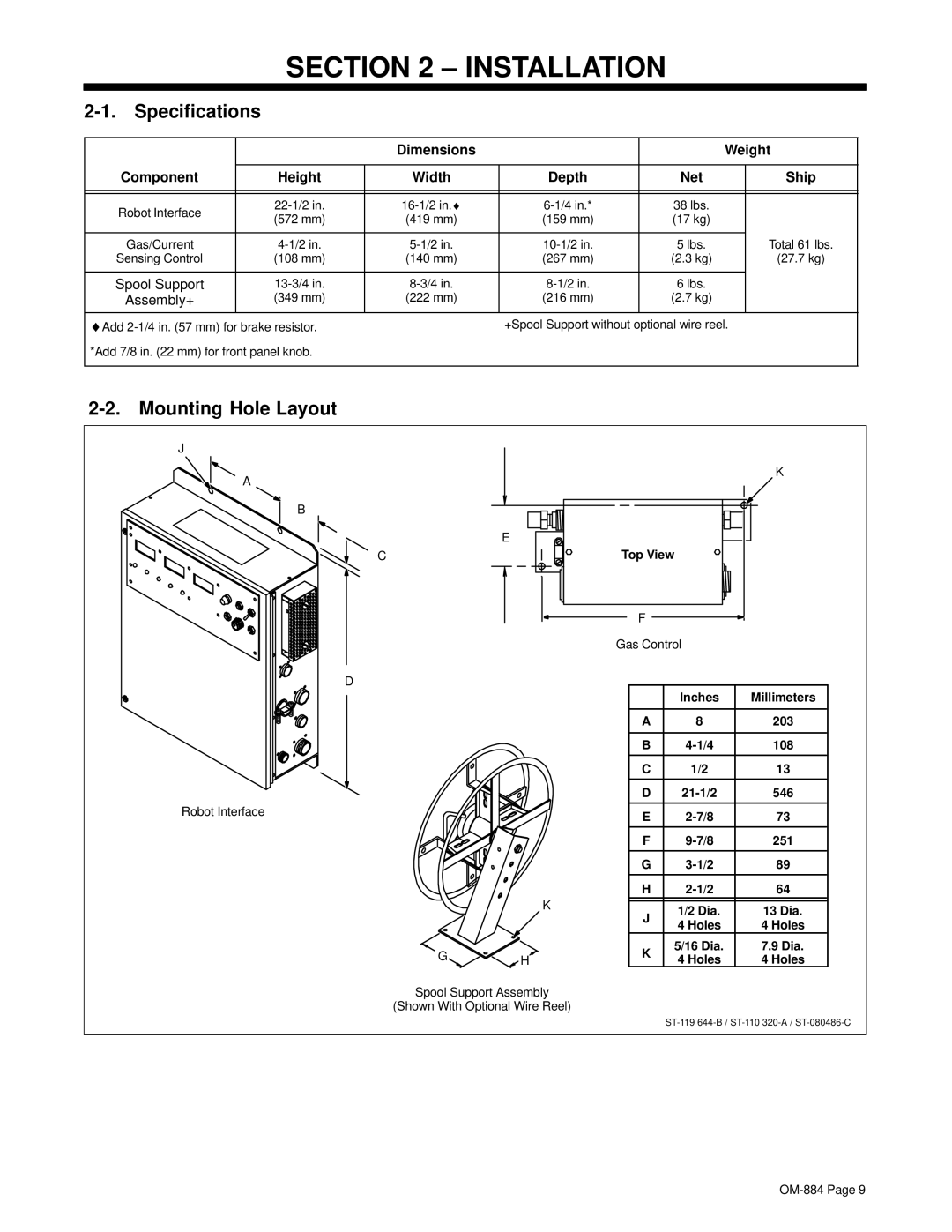
2-2. Mounting Hole Layout
J
A
B
E
C
D
Robot Interface
K
GH
Spool Support Assembly
(Shown With Optional Wire Reel)
K
Top View
F
Gas Control
| Inches | Millimeters | |
|
|
| |
A | 8 | 203 | |
|
|
| |
B | 108 | ||
|
|
| |
C | 1/2 | 13 | |
|
|
| |
D | 546 | ||
|
|
| |
E | 73 | ||
|
|
| |
F | 251 | ||
|
|
| |
G | 89 | ||
|
|
| |
H | 64 | ||
|
|
| |
J | 1/2 Dia. | 13 Dia. | |
4 Holes | 4 Holes | ||
| |||
K | 5/16 Dia. | 7.9 Dia. | |
4 Holes | 4 Holes | ||
|
