INSTALLATION AND WIRING
2.2.4 Connection to the PU connector
(1) When connecting the operation panel or parameter unit using a connection cable
<Recommended cable connector>
•Parameter unit connection cable
•Connector: RJ45 connector
Example:
• Cable: Cable conforming to EIA568 (e.g.
Example: SGLPEV 0.5mm×4P, MITSUBISHI CABLE INDUSTRIES, LTD.
Note: The maximum wiring length is 20m (65.62 feet).
(2) For RS-485 communication
With the operation panel disconnected, the PU connector can be used for communication operation from a personal computer etc.
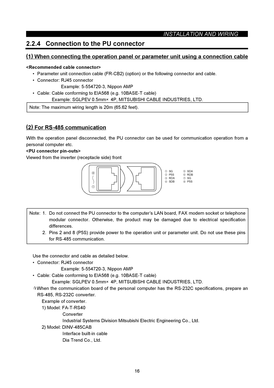
<PU connector pin-outs>
Viewed from the inverter (receptacle side) front
⑧ | ① SG | ⑤ SDA | |
② P5S | ⑥ RDB | ||
| |||
| ③ RDA | ⑦ SG | |
| ④ SDB | ⑧ P5S |
①
Note: 1. Do not connect the PU connector to the computer’s LAN board, FAX modem socket or telephone modular connector. Otherwise, the product may be damaged due to electrical specification differences.
2.Pins 2 and 8 (P5S) provide power to the operation unit or parameter unit. Do not use these pins for
Use the connector and cable as detailed below.
• Connector: RJ45 connector
Example:
• Cable: Cable conforming to EIA568 (e.g.
Example: SGLPEV 0.5mm×4P, MITSUBISHI CABLE INDUSTRIES, LTD.
When the communication board of the personal computer has the
Example of converter.
1)Model:
Industrial Systems Division Mitsubishi Electric Engineering Co., Ltd.
2)Model:
Interface
Dia Trend Co., Ltd.
16