SPECIFICATIONS
 Operation panel
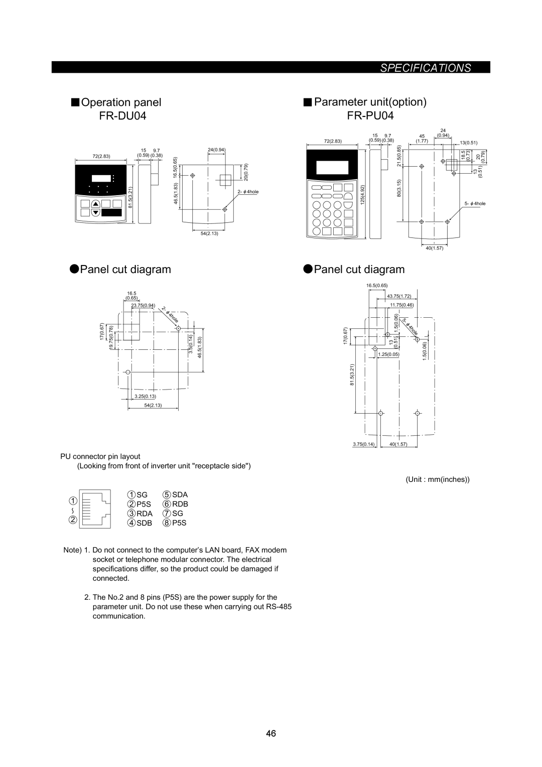
 FR-DU04
 Parameter unit(option)
 FR-PU04
72(2.83)
|
|
| 24 |
15 | 9.7 | 45 | (0.94) |
(0.59) (0.38) | (1.77) |
| |
13(0.51) |
72(2.83)
81.5(3.21)
15 | 9.7 | 24(0.94) |
(0.59) (0.38) | 16.5(0.65) | |
|
| |
|
| 46.5(1.83) |
|
| 54(2.13) |
![]() 20(0.79)
20(0.79)
2- ![]() 4hole
4hole
125(4.92)
21.5(0.85) |
80(3.15) |
18.5 | (0.73) |
| (0.79) | ||
| 20 | ||||
|
|
| |||
|
|
| 13 | (0.51) | |
|
|
| |||
5- ![]() 4hole
4hole
40(1.57)
 Panel cut diagram
16.5
(0.65)
|
| 23.75(0.94) |
|
|
| 2 |
|
|
| - |
|
17(0.67) |
| 4hole |
|
19.75(0.78) | 3.5(0.14) | 46.5(1.83) |
3.25(0.13)
54(2.13)
PU connector pin layout
(Looking from front of inverter unit "receptacle side")
1 | 1 | SG | 5 | SDA | |
2 | P5S | 6 | RDB | ||
| |||||
2 | 3 | RDA | 7 | SG | |
4 | SDB | 8 | P5S | ||
|
Note) 1. Do not connect to the computer’s LAN board, FAX modem socket or telephone modular connector. The electrical specifications differ, so the product could be damaged if connected.
2.The No.2 and 8 pins (P5S) are the power supply for the parameter unit. Do not use these when carrying out
communication.
![]() Panel cut diagram
Panel cut diagram
| 16.5(0.65) |
|
|
| 43.75(1.72) | ||
| 11.75(0.46) | ||
|
| 1.5(0.06) | 4hole |
|
|
| 5 |
17(0.67) |
|
| - |
13 | (0.51) | 1.5(0.06) | |
| 1.25(0.05) |
| |
| 81.5(3.21) |
|
|
3.75(0.14) |
| 40(1.57) |
(Unit : mm(inches))
46