INSTALLATION AND WIRING
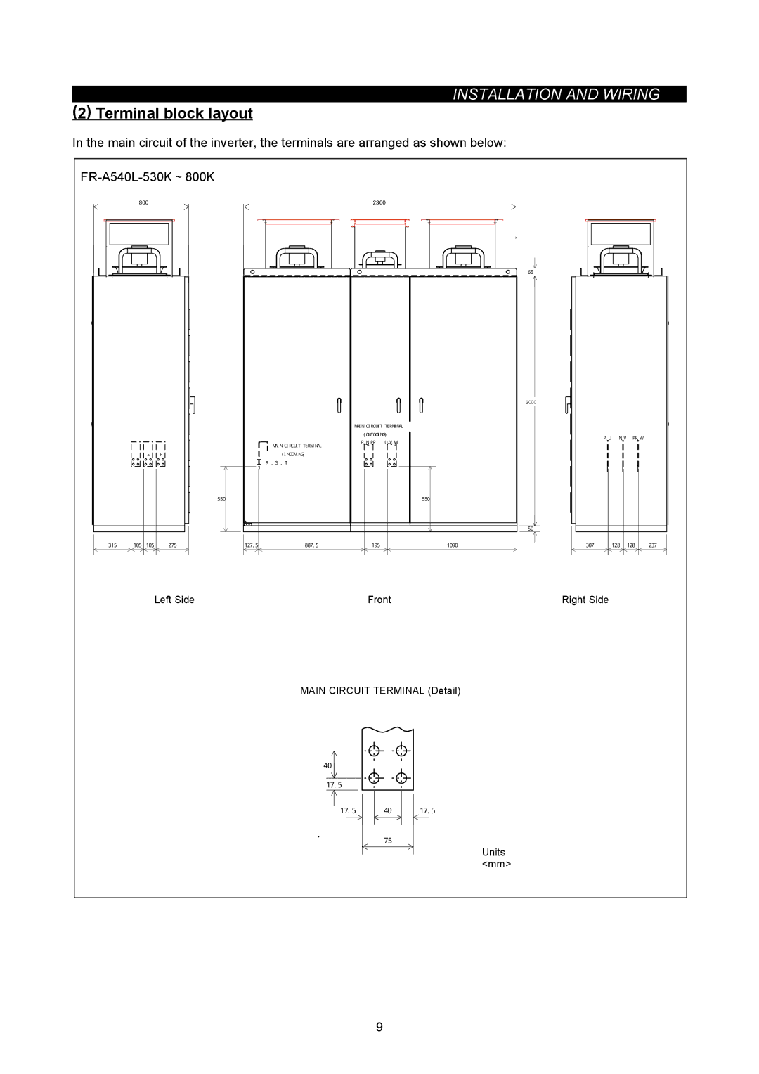
(2) Terminal block layout
In the main circuit of the inverter, the terminals are arranged as shown below:
|
|
|
|
|
|
|
| ||||
| 800 |
|
|
| 2300 |
|
|
|
|
| |
| 800 |
|
|
|
| 2300 |
|
|
|
|
|
|
|
|
|
|
|
|
| 65 |
|
|
|
|
|
|
|
|
|
|
| 21002000 |
|
|
|
|
|
|
|
| MAIN CIRCUIT TERMINAL |
|
|
|
|
| |
|
|
|
|
|
| (OUTGOING) |
| P,U | N,V | PR,W |
|
|
|
|
|
|
| P,N,PR U,V,W |
|
| |||
|
|
|
|
| MAIN CIRCUIT TERMINAL |
|
|
|
|
| |
|
|
|
|
|
|
|
|
|
|
| |
| T | S | R |
| (INCOMING) |
|
|
|
|
|
|
|
|
|
|
| R,S,T |
|
|
|
|
|
|
|
|
|
| 550 |
|
| 550 |
|
|
|
|
|
|
|
|
|
|
|
| 50 |
|
|
|
315 | 105 | 105 | 275 | 127.5 | 887.5 | 195 | 1090 | 307 | 128 | 128 | 237 |
|
|
| Left Side |
|
| Front |
| Right Side |
|
|
|
|
|
|
|
| MAIN CIRCUIT TERMINAL (Detail) |
|
|
|
| ||
|
|
|
|
| 40 |
|
|
|
|
|
|
|
|
|
|
| 17.5 |
|
|
|
|
|
|
|
|
|
|
| 17.5 | 40 | 17.5 |
|
|
|
|
|
|
|
|
|
| 75 |
|
|
|
|
|
|
|
|
|
|
|
|
| Units |
|
|
|
|
|
|
|
|
|
|
| <mm> |
|
|
|
|
|
|
|
|
| 9 |
|
|
|
|
|
