SPECIFICATIONS
6.1.2 | Common specifications |
|
| |||||||
|
|
|
|
|
|
| ||||
|
|
|
|
|
|
| ||||
|
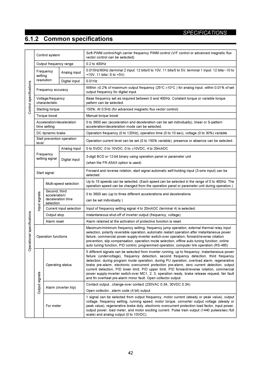
| Control system |
| |||||||
|
|
| vector control can be selected) |
|
| |||||
|
|
|
|
|
|
|
| |||
|
|
|
|
|
|
|
| |||
|
| Output frequency range | 0.2 to 400Hz |
|
| |||||
|
|
|
|
|
|
| ||||
|
| Frequency |
| Analog input | 0.015Hz/60Hz (terminal 2 input: 12 bits/0 to 10V, 11 bits/0 to 5V, terminal 1 input: 12 bits/− 10 to | |||||
|
| setting |
| +10V, 11 bits/− 5 to +5V) |
|
| ||||
|
|
|
|
|
| |||||
| specifications | resolution |
| Digital input | 0.01Hz |
|
|
| ||
|
|
|
|
|
|
| ||||
|
|
|
|
|
|
|
|
|
| |
|
|
|
|
|
| ± | ° | ± | ° | |
|
| Frequency accuracy | Within |
| 0.2% of maximum output frequency (25 C |
| 10 C ) for analog input, within 0.01% of set | |||
|
| output frequency for digital input |
|
| ||||||
|
|
|
|
|
|
|
| |||
|
|
|
|
| ||||||
|
| Voltage/frequency | Base frequency set as required between 0 and 400Hz. Constant torque or variable torque | |||||||
| Control | characteristic |
| pattern can be selected. |
|
| ||||
|
|
|
|
|
|
|
|
|
| |
| Starting torque |
| 150%: At 0.5Hz (for advanced magnetic flux vector control) | |||||||
|
|
| ||||||||
|
|
|
|
|
|
|
| |||
|
| Torque boost |
| Manual torque boost |
|
| ||||
|
|
|
|
| ||||||
|
| Acceleration/deceleration | 0 to 3600 sec (acceleration and deceleration can be set individually), linear or | |||||||
|
| time setting |
| acceleration/deceleration mode can be selected. |
|
| ||||
|
|
|
|
| ||||||
|
| DC dynamic brake | Operation frequency (0 to 120Hz), operation time (0 to 10 sec), voltage (0 to 30%) variable | |||||||
|
|
|
|
|
|
|
|
| ||
|
| Stall prevention operation | Operation current level can be set (0 to 150% variable), presence or absence can be selected. | |||||||
|
| level |
| |||||||
|
|
|
|
|
|
|
| |||
|
|
|
|
| Analog input | 0 to 5VDC, 0 to 10VDC, 0 to ± 10VDC, 4 to 20mADC | ||||
|
| Frequency |
|
|
|
|
|
|
| |
|
|
|
| |||||||
|
| setting signal |
| Digital input | ||||||
|
|
|
|
|
|
|
| |||
|
|
|
|
| (when the |
|
| |||
|
|
|
|
|
|
|
| |||
|
|
|
|
|
|
| ||||
|
| Start signal |
| Forward and reverse rotation, start signal automatic | ||||||
|
|
| selected. |
|
| |||||
|
|
|
|
|
|
|
| |||
|
|
|
|
|
|
| ||||
|
|
| Up to 15 speeds can be selected. (Each speed can be selected in the range of 0 to 400Hz. The | |||||||
|
|
| operation speed can be changed from the operation panel or parameter unit during operation.) | |||||||
|
|
|
|
|
| |||||
|
|
|
|
|
|
|
|
| ||
|
| signals | Second, third | can be set individually.) |
|
| ||||
|
| deceleration time |
|
| ||||||
|
|
| acceleration/ | 0 to 3600 sec (up to three different accelerations and decelerations | ||||||
|
|
|
|
|
|
|
| |||
|
| Input | selection |
|
|
|
|
|
| |
|
| Current input selection | Input of frequency setting signal 4 to 20mADC (terminal 4) is selected. | |||||||
| specifications |
|
|
|
|
|
|
|
| |
|
| Output stop | Instantaneous | |||||||
|
|
| ||||||||
|
|
|
|
| ||||||
|
|
| Alarm reset | Alarm retained at the activation of protective function is reset. | ||||||
|
|
|
|
|
|
| ||||
|
|
|
|
|
| Maximum/minimum frequency setting, frequency jump operation, external thermal relay input | ||||
| Operational |
|
|
|
| selection, polarity reversible operation, automatic restart operation after instantaneous power | ||||
| Operation functions | failure, commercial power | ||||||||
|
| |||||||||
|
|
|
|
|
| prevention, slip compensation, operation mode selection, offline auto tuning function, online | ||||
|
|
|
|
|
| auto tuning function, PID control, programmed operation, computer link operation | ||||
|
|
|
|
|
|
| ||||
|
|
|
|
|
| 5 different signals can be selected from inverter running, up to frequency, instantaneous power | ||||
|
|
|
|
|
| failure (undervoltage), frequency detection, second frequency detection, third frequency | ||||
|
|
|
|
|
| detection, during program mode operation, during PU operation, overload alarm, regenerative | ||||
|
|
| Operating status | brake | ||||||
|
| signals |
|
|
| current detection, PID lower limit, PID upper limit, PID forward/reverse rotation, commercial | ||||
|
|
|
|
| power | |||||
|
|
|
|
| and fin overheat | |||||
|
|
|
|
|
| |||||
|
|
|
|
|
|
| ||||
|
| Output | Alarm (inverter trip) | Contact | ||||||
|
| Open collector...alarm code (4 bit) output |
|
| ||||||
|
|
|
|
| ||||||
|
|
|
|
|
|
|
| |||
|
|
|
|
|
|
| ||||
|
|
|
|
|
| 1 signal can be selected from output frequency, motor current (steady or peak value), output | ||||
|
|
|
|
|
| voltage, frequency setting, running speed, motor torque, converter output voltage (steady or | ||||
|
|
| For meter |
| peak value), regenerative brake duty, electronic overcurrent protection load factor, input power, | |||||
|
|
|
|
|
| output power, load meter, and motor exciting current. Pulse train output (1440 pulses/sec./full | ||||
|
|
|
|
|
| scale) and analog output (0 to 10VDC). |
|
| ||
|
|
|
|
|
|
|
|
|
|
|
42