FX Series Programmable Controllers | Devices in Detail 4 |
4.13.1Modifying a Constant
Constants can be modified just as easily as data registers or bit devices. If, for example, the constant K20 was actually written K20V the final result would equal:
K20 + the contents of V
Example:
K20
If V = 3276 then K20V ➭ V (3276) 3296
4.13.2Misuse of the Modifiers
Modifying Kn devices when Kn forms part of a device description such as KnY is not possible, i.e. while the following use of modifiers is permitted;
K3Z
K1M10V
Y20Z
Statements of the form:
K4ZY30
are not acceptable.
• Modifiers cannot be used for parameters entered into any of the 20 basic instructions, i.e. LD, AND, OR etc.
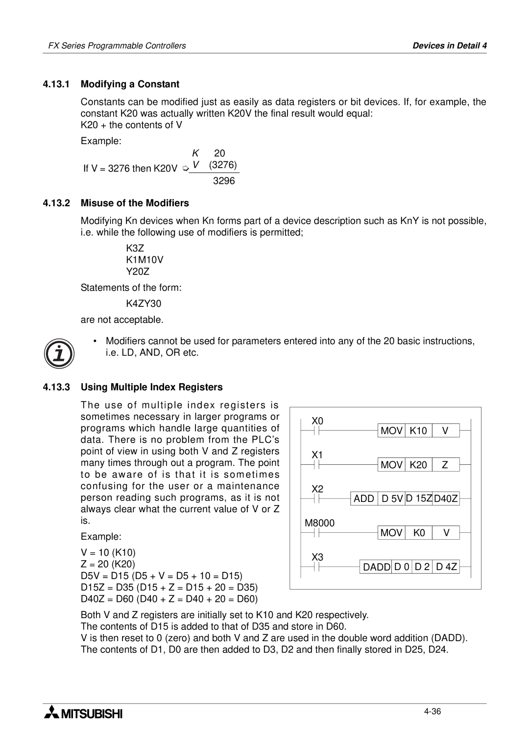
4.13.3 Using Multiple Index Registers |
The use of multiple index registers is |
sometimes necessary in larger programs or |
programs which handle large quantities of |
data. There is no problem from the PLC’s |
point of view in using both V and Z registers |
many times through out a program. The point |
to be aware of is that it is som etimes |
confusing for the user or a maintenance |
X0
X1
X2
MOV K10 ![]() V
V
MOV K20 ![]() Z
Z
person reading such programs, as it is not |
always clear what the current value of V or Z |
is. |
Example: |
V = 10 (K10) |
Z = 20 (K20) |
D5V = D15 (D5 + V = D5 + 10 = D15) |
D15Z = D35 (D15 + Z = D15 + 20 = D35) |
D40Z = D60 (D40 + Z = D40 + 20 = D60) |
![]()
![]()
![]() ADD D 5V D 15Z D40Z
ADD D 5V D 15Z D40Z ![]()
M8000
MOV K0 V
X3
![]()
![]() DADD D 0 D 2 D 4Z
DADD D 0 D 2 D 4Z
Both V and Z registers are initially set to K10 and K20 respectively. The contents of D15 is added to that of D35 and store in D60.
V is then reset to 0 (zero) and both V and Z are used in the double word addition (DADD). The contents of D1, D0 are then added to D3, D2 and then finally stored in D25, D24.